


 Home
-
Blog
-
Why CLTE-MW PCB for Thin 5G and mmWave Designs? Low Loss, Thin Cores, and Stable Phase
Home
-
Blog
-
Why CLTE-MW PCB for Thin 5G and mmWave Designs? Low Loss, Thin Cores, and Stable Phase
Why CLTE-MW PCB for Thin 5G and mmWave Designs? Low Loss, Thin Cores, and Stable Phase
 May 15,2026
When 5G millimeter-wave designers talk about challenges, two issues come up constantly: glass weave effect and board thickness.
Standard laminates often cannot achieve the very thin dielectric layers required for controlled impedance at 28GHz, 39GHz, or 77GHz. And even when they do, the weave of the glass reinforcement can cause phase inconsistencies across the board.
CLTE-MW was designed to solve both problems.
1.The Thin Core Advantage
Rogers CLTE-MW laminate is available in seven thickness options, from 3 to 10 mils (0.075mm to 0.254mm) . This range is specifically chosen for millimeter-wave applications where signal-to-ground spacing directly impacts performance.
Why does thickness matter? At mmWave frequencies, the distance between the signal trace and the reference ground determines characteristic impedance. Thinner laminates allow narrower trace widths for the same impedance, which reduces board size and improves routing density. For 5G antenna arrays with dozens of elements, this matters.
The seven thickness options mean designers can select the exact spacing needed for their target impedance, without compromising on other design parameters.
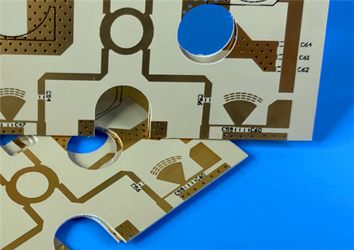
CLTE-MW Immerion Gold PCB
2.Solving the Glass Weave Effect
Standard woven glass laminates have a problem at high frequencies. The gaps between glass fibers create variations in local dielectric constant. As a signal travels along a microstrip line, it sees alternating areas of higher and lower Dk. At low frequencies, this averages out. At mmWave frequencies, it causes phase errors and signal distortion.
CLTE-MW uses spread glass reinforcement combined with high filler loading. Spread glass means the glass fibers are distributed more evenly across the laminate, with smaller gaps between bundles. The high filler loading further homogenizes the dielectric.
The result is minimized glass weave effect on electromagnetic wave propagation. For phase-sensitive applications like beamforming antenna arrays, this translates to consistent element-to-element performance.
3.Electrical and Thermal Properties
Property |
CLTE-MW Value |
Why It Matters |
Dissipation Factor @10GHz |
0.0015 |
Low enough for mmWave designs up to 77GHz+ |
Z-axis CTE |
30 ppm/°C |
Supports PTH reliability under thermal cycling |
Thermal Conductivity |
0.42 W/(m·K) |
Adequate for moderate power levels |
Flammability |
UL94 V-0 |
Compliant with commercial and aerospace requirements |
The dissipation factor of 0.0015 at 10GHz places CLTE-MW in the low-loss category. It is not ultra-low-loss (like RO3003 at 0.0010), but it is significantly better than standard FR4 (0.025) or mid-loss materials. For most 5G infrastructure and aerospace applications, this loss level is perfectly acceptable.
The Z-axis CTE of 30 ppm/°C is critical for plated through-hole reliability. When the board undergoes thermal cycling, the dielectric expands at a rate close to copper (17 ppm/°C) and far below standard PTFE materials (often >100 ppm/°C). This means vias are less likely to crack over temperature cycles.
4. Applications
CLTE-MW is suited for designs where thickness control and phase stability are priorities. Typical applications include:
Commercial communications and avionics
Military and aerospace applications
Microwave feed networks
Phase-sensitive electronic structures (e.g., phased array antennas)
Satellite communication systems
Passive components including couplers, filters, and baluns
For aerospace and military applications, the UL94 V-0 flammability rating and stable mechanical performance under thermally challenging environments are essential qualifications.
5.Benefits
The combination of thin core options, spread glass reinforcement, and low-loss dielectric delivers several practical benefits:
Low loss designs. With Df of 0.0015, CLTE-MW enables efficient signal transmission at mmWave frequencies. Insertion loss per inch is predictable and consistent.
Excellent PTH reliability. The Z-axis CTE of 30 ppm/°C means plated through-holes survive thermal cycling without barrel cracking. For boards that go through lead-free assembly (peak 260°C) and then operate in outdoor environments with wide temperature swings, this is a key differentiator.
Good heat dissipation. Thermal conductivity of 0.42 W/(m·K) is higher than standard FR4 (approx 0.3) and adequate for most commercial applications.
Commercial compatibility. CLTE-MW is designed for cost-effective manufacturing. It processes with standard PTFE fabrication techniques and is compatible with commercial production volumes.
Reliable mechanical performance. The spread glass reinforcement and filler loading create a dimensionally stable laminate that maintains its properties under thermal stress.
6.Conclusion
CLTE-MW fills a specific niche in the mmWave material landscape. It is not the lowest-loss material available, nor is it the cheapest. But for applications that require thin cores (3 to 10 mils), stable phase performance, and reliable PTHs under thermal cycling, it offers a balanced solution.
For 5G infrastructure, satellite communications, and aerospace systems where thickness constraints and glass weave effects are real design problems, CLTE-MW provides an engineered answer.