

 Home
-
Microwave PCB
-
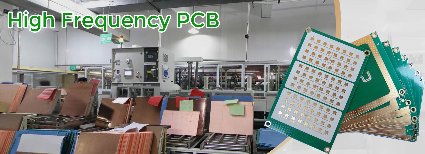
Rogers RT/duroid 6035HTC Microwave PCB 2-Layer 10mil Core Structure Immersion Gold Coating for Filters
Home
-
Microwave PCB
-
Rogers RT/duroid 6035HTC Microwave PCB 2-Layer 10mil Core Structure Immersion Gold Coating for Filters
Rogers RT/duroid 6035HTC Microwave PCB 2-Layer 10mil Core Structure Immersion Gold Coating for Filters
Printed Circuit Boards are custom-made products; the images and specifications provided are for reference only.
General Description
Rogers RT/duroid 6035HTC high - frequency PCB materials, which are ceramic - filled PTFE composites, are made for high - power RF and microwave applications. Rogers RT/duroid 6035HTC PCB possess a thermal conductivity that is approximately 2.4 times higher than the standard RT/duroid 6000 products. The copper foil (electrodeposited and reverse - treated) of RT/duroid 6035HTC laminates shows excellent long - term thermal stability. Therefore, RT/duroid 6035HTC PCBs are an ideal choice for high - power applications.
.jpg)
Features/Benefits:
- High Thermal conductivity
Improved dielectric heat dissipation enables lower operating temperatures for high power applications
- Low loss tangent
Excellent high frequency performance
- Thermally stable low profile and reverse treat copper foil
Lower insertion loss and excellent thermal stability of traces
- Advanced filler system
Improved drill ability and extended tool life compared to alumina containing circuit materials

Some Typical Applications:
- High Power RF and Microwave Amplifiers
- Power amplifiers, Couplers, Filters
- Combiners, Power Dividers
PCB Capability (RT/duroid 6035HTC)
PCB Capability (RT/duroid 6035HTC) |
|
PCB Material: |
Ceramic-filled PTFE composites |
Designation: |
RT/duroid 6035HTC |
Dielectric constant: |
3.50±0.05 |
Layer count: |
Double Layer, Multilayer, Hybrid PCB |
Copper weight: |
0.5oz (17 µm), 1oz (35µm), 2oz (70µm) |
Laminate thickness: |
10mil (0.254mm), 20mil(0.508mm), 30mil (0.762mm), 60mil(1.524mm) |
PCB size: |
≤400mm X 500mm |
Solder mask: |
Green, Black, Blue, Yellow, Red etc. |
Surface finish: |
Bare copper, HASL, ENIG, Immersion silver, Immersion tin, OSP etc.. |
Data Sheet of RT/duroid 6035HTC
| Property | Typical Value RT/duroid 6035HTC | Direction | Unit | Condition | Test Method |
| Dielectric Constant, εr Process | 3.50 ± 0.05 | Z | - | 10 GHz/23°C | IPC-TM-650 2.5.5.5 Clamped Stripline |
| Dielectric Constant, εr Design |
3.6 | Z | - | 8 GHz - 40 GHz | Differential Phase Length Method |
| Dissipation Factor, | 0.0013 | Z | - | 10 GHz/23°C | IPC-TM-650, 2.5.5.5 |
| Thermal Coefficient of εr | -66 | Z | ppm/°C | -50°C to 150°C | mod IPC-TM-650, 2.5.5.5 |
| Dielectric Strength | 835 | - | V/Mil | 15 mil thickness | IPC-TM-650, 2.5.6.2 |
| Breakdown Voltage | 12.59 | - | kV | 15 mil thickness | IPC-TM-650, 2.5.6 |
| Volume Resistivity | 108 | - | MΩ•cm | COND A | IPC-TM-650, 2.5.17.1 |
| Surface Resistivity | 108 | - | MΩ | COND A | IPC-TM-650, 2.5.17.1 |
| Tensile Modulus | 329 244 |
MD CMD |
kpsi | 40 hrs @ 23°C/50RH | ASTM D638 |
| Dimensional Stability | -0.11 -0.08 |
CMD MD |
mm/m (mils/inch) |
0.030” 1 oz EDC foil Thickness after etch +E4/105 |
IPC-TM-650, 2.4.39A |
| Coefficient of Thermal Expansion (-55 to 288 °C) |
19 | X | ppm/°C | 23°C/50% RH | IPC-TM-650 2.4.41 |
| 19 | Y | ||||
| 39 | Z | ||||
| Thermal Conductivity | 1.44 | - | W/m/K | 80°C | ASTM C518 |
| Moisture Absorption | 0.06 | - | % | D24/23 | IPC-TM-650 2.6.2.1 ASTM D570 |
| Density | 2.2 | - | gm/cm3 | 23°C | ASTM D-792 |
| Copper Peel Strength | 7.9 | - | pli | 20 sec.@ 288°C | IPC-TM-650 2.4.8 |
| Flammability | V-0 | - | - | - | UL 94 |
| Lead-Free Process Compatible |
YES |