

 Home
-
Antenna PCB
-
Rogers RT/duroid 6002 PCB Built on 20mil Double-layer laminate With HASL Lead Free for Ground Based and Airborne Radar Systems
Home
-
Antenna PCB
-
Rogers RT/duroid 6002 PCB Built on 20mil Double-layer laminate With HASL Lead Free for Ground Based and Airborne Radar Systems
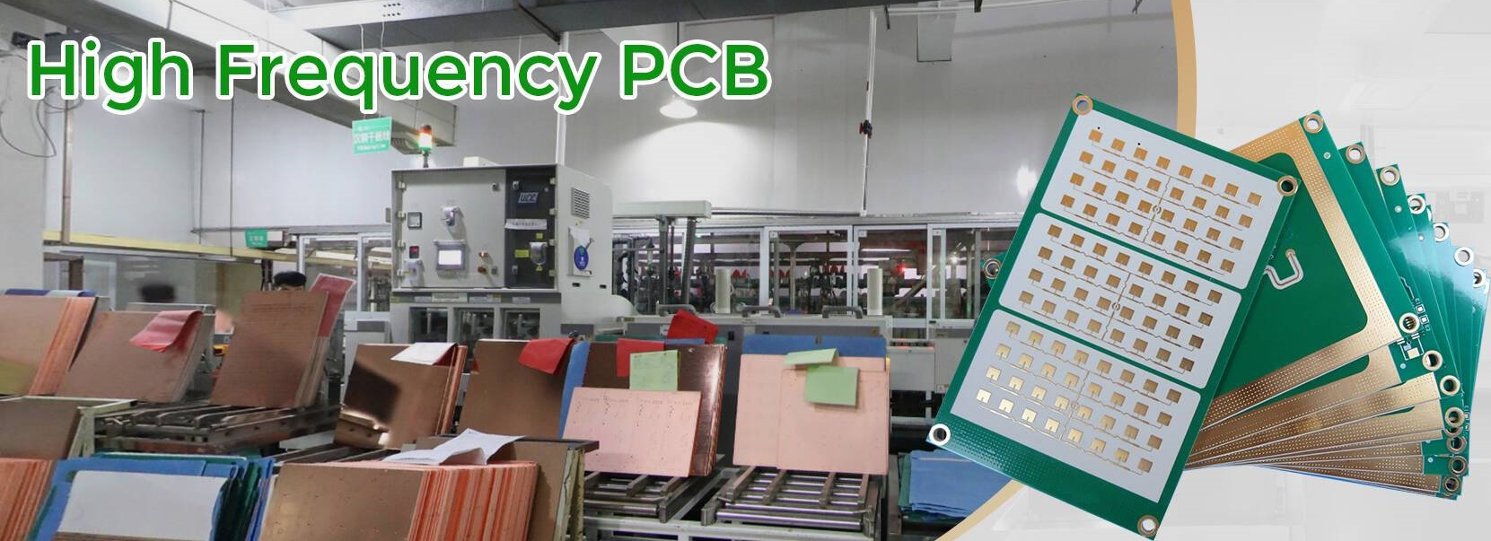
Rogers RT/duroid 6002 PCB Built on 20mil Double-layer laminate With HASL Lead Free for Ground Based and Airborne Radar Systems
Printed Circuit Boards are custom-made products; the images and specifications provided are for reference only.
Brief Introduction
Rogers RT/duroid 6002 PCB stands as a groundbreaking low-loss, low-dielectric-constant laminate that delivers exceptional electrical and mechanical properties for demanding microwave applications. This advanced Rogers RT/duroid 6002 material enables the design of complex microwave structures with outstanding reliability and electrical stability, making it an ideal choice for high-frequency circuits requiring precision performance.
Engineered for thermal stability, RT/duroid 6002 PCB exhibits an extremely low thermal coefficient of dielectric constant across a wide temperature range from -55℃ to +150℃. This crucial characteristic ensures the electrical stability necessary for precision components like filters, oscillators, and delay lines in modern microwave systems. The material's low Z-axis coefficient of thermal expansion guarantees exceptional plated-through-hole reliability, demonstrated through rigorous testing that shows zero via failures after 5000+ temperature cycles from -55℃ to 125℃.
Rogers RT/duroid 6002 PCB achieves remarkable dimensional stability (0.2 to 0.5 mils/inch) by precisely matching X and Y coefficient of expansion to copper, effectively eliminating the need for double etching to maintain tight positional tolerances. The material's low tensile modulus significantly reduces stress on solder joints while allowing expansion to be constrained by low CTE metals, substantially enhancing surface mount reliability.
The unique properties of Rogers RT/duroid 6002 make it particularly suitable for challenging applications including flat and non-planar antenna structures, complex multilayer circuits with inter-layer connections, and sophisticated microwave circuits for aerospace systems operating in hostile environments. Rogers RT/duroid 6002 continues to set the standard for reliability and performance in advanced microwave PCB applications.
.jpg)
Typical applications:
1. Airborne radar systems
2. Beam forming networks
3. Commercial airline collision avoidance
4. Global positioning systems antennas
5. Ground base systems
6. High reliability complex multi-layer circuits
7. Phased array antennas
8. Power backplanes
PCB Specifications
| Rogers RT/duroid 6002 20mil 0.508mm High Frequency PCB for Ground Based and Airborne Radar Systems | |
| PCB SIZE | 79 x 21 mm=1PCS |
| BOARD TYPE | Double sided PCB |
| Number of Layers | 2 layers |
| Surface Mount Components | YES |
| Through Hole Components | NO |
| LAYER STACKUP | copper ------- 18um(0.5 oz)+plate TOP layer |
| RT/duroid 6002 0.508mm | |
| copper ------- 18um(0.5 oz)+plate BOT layer | |
| TECHNOLOGY | |
| Minimum Trace and Space: | 10 mil / 10 mil |
| Minimum / Maximum Holes: | 0.4 mm / 2.2mm |
| Number of Different Holes: | 1 |
| Number of Drill Holes: | 1 |
| Number of Milled Slots: | 0 |
| Number of Internal Cutouts: | 0 |
| Impedance Control: | no |
| Number of Gold finger: | 0 |
| BOARD MATERIAL | |
| Glass Epoxy: | RT/duroid 6002 0.508mm |
| Final foil external: | 1 oz |
| Final foil internal: | 1 oz |
| Final height of PCB: | 0.6 mm ±0.06 |
| PLATING AND COATING | |
| Surface Finish | HASL Lead free |
| Solder Mask Apply To: | NO |
| Solder Mask Color: | NO |
| Solder Mask Type: | NO |
| CONTOUR/CUTTING | Routing |
| MARKING | |
| Side of Component Legend | N/A |
| Colour of Component Legend | N/A |
| Manufacturer Name or Logo: | N/A |
| VIA | Plated through hole(PTH), minimum size 0.4mm. |
| FLAMIBILITY RATING | UL 94-V0 Approval MIN. |
| DIMENSION TOLERANCE | |
| Outline dimension: | 0.0059"" |
| Board plating: | 0.0029"" |
| Drill tolerance: | 0.002"" |
| TEST | 100% Electrical Test prior shipment |
| TYPE OF ARTWORK TO BE SUPPLIED | email file, Gerber RS-274-X, PCBDOC etc |
| SERVICE AREA | Worldwide, Globally. |
Data Sheet of Rogers 6002 (RT/duroid 6002)
| RT/duroid 6002 Typical Value | |||||
| Property | RT/duroid 6002 | Direction | Units | Condition | Test Method |
| Dielectric Constant,εProcess | 2.94±0.04 | Z | 10 GHz/23℃ | IPC-TM-650 2.5.5.5 | |
| Dielectric Constant,εDesign | 2.94 | 8GHz to 40 GHz | Differential Phase Length Method | ||
| Dissipation Factor,tanδ | 0.0012 | Z | 10 GHz/23℃ | IPC-TM-650 2.5.5.5 | |
| Thermal Coefficient of ε | +12 | Z | ppm/℃ | 10 GHz 0℃-100℃ | IPC-TM-650 2.5.5.5 |
| Volume Resistivity | 106 | Z | Mohm.cm | A | ASTM D 257 |
| Surface Resistivity | 107 | Z | Mohm | A | ASTM D 257 |
| Tensile Modulus | 828(120) | X,Y | MPa(kpsi) | 23℃ | ASTM D 638 |
| Ultimate Stress | 6.9(1.0) | X,Y | MPa(kpsi) | ||
| Ultimate Strain | 7.3 | X,Y | % | ||
| Compressive Modulus | 2482(360) | Z | MPa(kpsi) | ASTM D 638 | |
| Moisture Absorption | 0.02 | % | D48/50 | IPC-TM-650 2.6.2.1 ASTM D 570 |
|
| Thermal Conductivity | 0.6 | W/m/k | 80℃ | ASTM C518 | |
| Coefficient of Thermal Expansion (-55 to 288℃) |
16 16 24 |
X Y Z |
ppm/℃ | 23℃/50% RH | IPC-TM-650 2.4.41 |
| Td | 500 | ℃ TGA | ASTM D 3850 | ||
| Density | 2.1 | gm/cm3 | ASTM D 792 | ||
| Specific Heat | 0.93(0.22) | j/g/k (BTU/ib/OF) |
Calculated | ||
| Copper Peel | 8.9(1.6) | Ibs/in.(N/mm) | IPC-TM-650 2.4.8 | ||
| Flammability | V-0 | UL 94 | |||
| Lead-free Process Compatible | Yes |