


 Home
Home
Why Choose RO3003 and FR4 Hybrid PCB for 77GHz Radar and RF Communication?
 May 7,2026
In the world of high-frequency electronics, material selection is not just a parameter—it is the performance. As we push the boundaries of automotive autonomy (ADAS) and next-gen telecom infrastructure (5G/6G) , the Printed Circuit Board (PCB) must do more than just hold components; it must act as a precision waveguide.
For engineers developing 77GHz millimeter-wave radar and satellite communication systems, the challenge is often balancing ultra-low signal loss with cost-effective manufacturing. Enter the Rogers RO3003 and TG170 FR4 4-Layer Hybrid PCB with Immersion Silver finish—a solution engineered for the real world, where physics meets commercial viability.
In this technical deep dive, we explore why this specific hybrid stack-up is becoming the industry standard for high-reliability RF modules.
1.The "Best of Both Worlds": Hybrid Dielectric Stack-up
Why compromise on cost when you don't have to compromise on signal integrity? A standard FR4 board cannot handle 77GHz signals due to high dielectric loss (Df typically >0.02 at 10GHz), while a full Rogers PCB board can be prohibitively expensive for production volumes—often 5-10x the cost of standard FR4. The hybrid solution solves this by placing premium materials only where they matter: the RF signal path.
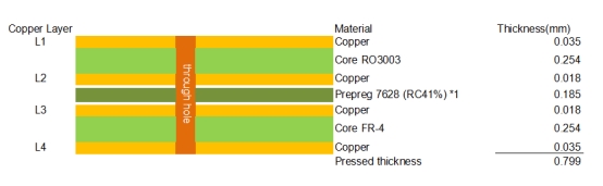
This 4-Layer design utilizes a strategic stack-up:
Layer 1 (Top, 0.035mm copper on RO3003 core):RF transmission, microstrip patch antennas, and signal reception.
Layer 2 (0.018mm copper on RO3003 core):Continuous ground plane, minimizing parasitic inductance and providing a clean reference for stripline designs.
Prepreg 7628 (RC41%, 0.185mm):Dielectric isolation between the high-frequency RO3003 section and the standard FR-4 section.
Layer 3 (0.018mm copper on FR-4 core):Power distribution and intermediate signal routing.
Layer 4 (Bottom, 0.035mm copper on FR-4 core):Control signals and optional component placement.
The total pressed thickness of the stack-up is 0.799mm.
The Engineering Advantage: Rogers RO3003 laminate features a Dielectric Constant (Dk) of 3.00 ± 0.04 (process value) at 10GHz, which remains stable from DC to 77GHz and across a temperature range of -50°C to +150°C with a thermal coefficient of just -3 ppm/°C. Unlike standard PTFE glass materials that exhibit a step change in Dk near room temperature, the ceramic-filled nature of RO3003 ensures phase stability—critical for high-resolution radar imaging.
Layer/Structure |
Material |
Thickness (mm) |
Key Function |
L1 Copper |
Copper |
0.035 |
RF antenna & signal trace |
Core (L1-L2) |
Rogers RO3003 |
0.254 |
High-frequency RF substrate |
L2 Copper |
Copper |
0.018 |
RF ground plane |
Prepreg |
7628 (RC41%) |
0.185 |
Lamination bonding & dielectric isolation |
L3 Copper |
Copper |
0.018 |
Power/control signal routing |
Core (L3-L4) |
FR-4 |
0.254 |
Low-cost support layer |
L4 Copper |
Copper |
0.035 |
Control signals & component placement |
Total Pressed Thickness |
— |
0.799 |
— |
2.Surviving the "Thermal Shock": Why CTE Matching Matters
One of the leading causes of RF PCB failure in the field is via barrel cracking caused by Z-Axis expansion. In a hybrid board, the RF material and the FR4 material expand at different rates. If the materials aren't matched, thermal cycling (e.g., a cold winter start at -40°C to a hot engine bay at +85°C) will snap plated through-holes (PTHs) after as few as 200-300 cycles—catastrophic failure for an automotive module rated for 10+ years.
Here is why the RO3003 + TG170 combination excels. First, Rogers RO3003 has a coefficient of thermal expansion of 17 ppm/°C on the X-axis and 16 ppm/°C on the Y-axis, closely matching that of copper (17 ppm/°C). This ensures copper traces won't delaminate or crack during reflow assembly (peak 260°C), with typical etch shrinkage less than 0.5 mils per inch after etch and bake. Second, with a Z-axis CTE of 25 ppm/°C (compared to >200 ppm/°C for softer PTFE materials like RT/duroid 5880), the expansion is well controlled, drastically improving PTH reliability in severe thermal environments. Third, the high glass transition temperature of TG170 FR4 (170°C) ensures the rigid section does not soften under lead-free reflow processes (peak 260°C), preventing warpage commonly seen in cheaper hybrid builds using standard TG135 FR4.
This combination is particularly critical for automotive radar modules mounted directly behind the front grille or bumper, where ambient temperatures swing from arctic winter cold to desert summer heat compounded by engine bay radiation.
3.Surface Finish Optimization: Why Immersion Silver Over ENIG?
In the high-frequency community, surface finish is often an afterthought—but it shouldn't be. While ENIG (Electroless Nickel Immersion Gold) is common for general-purpose PCBs, the nickel layer (typically 3-6 µm thick) between the copper and gold introduces significant insertion loss at mmWave frequencies due to the skin effect.
At 77GHz, the skin depth of copper is approximately 0.24 µm. The signal does not travel through the bulk of the conductor; it travels along the surface. When ENIG is applied, that signal encounters the nickel layer—a material with roughly 4-6x higher resistivity than copper—and suffers measurable attenuation.
Immersion Silver eliminates this problem through several key advantages. It deposits directly onto copper (0.2–0.5 µm thickness) with no nickel barrier, so the signal sees a continuous low-resistivity path. Silver has a bulk resistivity of approximately 1.59 µΩ-cm, even lower than copper (1.68 µΩ-cm). At RF frequencies, this translates to measurably lower insertion loss—typically 0.2–0.5 dB less loss per inch compared to ENIG at 77GHz. For microstrip patch antennas operating at 77GHz, surface flatness is critical, and Immersion Silver deposits uniformly (<5 µm variation), ensuring precise etching tolerances and consistent antenna resonance across thousands of boards. Additionally, many radar chipset manufacturers (Texas Instruments AWR series, NXP, Infineon) require aluminum or gold wire bonding for MMIC attachment. Immersion Silver provides a bondable surface suitable for these high-frequency ICs, whereas OSP (Organic Solderability Preservative) does not support wire bonding.
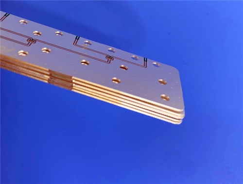
Design Note: Immersion Silver does require careful handling—it tarnishes when exposed to high humidity or sulfur for extended periods. For volume production with just-in-time (JIT) scheduling, this is rarely an issue. For long-term storage (6+ months), we recommend nitrogen-sealed packaging.
4.Electrical Performance: What the Numbers Mean for Your Design
Engineers care about specifications because they predict real-world behavior. Below are the official Rogers RO3003 parameters translated into system-level impact.
Parameter |
RO3003 Value (Official) |
System-Level Impact |
Dielectric Constant (Dk) @10GHz |
3.00 ± 0.04 (process) / 3.16 (design) |
Predictable impedance control for 50Ω traces |
Dissipation Factor (Df) @10GHz |
0.0010 |
Ultra-low signal attenuation – suitable up to 77GHz+ |
Thermal Coefficient of εr (-50°C to 150°C) |
-3 ppm/°C |
Minimal Dk drift across temperature extremes |
Thermal Conductivity |
0.50 W/m·K |
Efficient heat dissipation from power amplifiers |
Moisture Absorption (D48/50%) |
0.04% |
Dk stability in humid environments – no filter detuning |
Volume/Surface Resistivity |
1×10⁷ MΩ |
Excellent isolation between adjacent RF traces |
CTE - X / Y / Z |
17 / 16 / 25 ppm/°C |
Matched to copper; dimensional stability |
Real-world translation: The 0.0010 dissipation factor at 10GHz is among the lowest in commercially available microwave laminates. A 77GHz radar transmitting through a 10cm microstrip line on standard FR4 (Df≈0.025) would lose over 30% of its signal power (3+ dB). On this RO3003 hybrid PCB, the loss is under 0.5 dB—meaning the radar can detect objects from 200 meters away instead of 120 meters.
5.Application Spotlight: Where This PCB is Used
This specific stack-up is engineered for front-end hardware where every picosecond and every decibel matters. Rogers Corporation explicitly lists automotive radar (77GHz), ADAS, and 5G wireless infrastructure (mmWave) as target applications for RO3003 laminates.
Automotive 4D Imaging Radar (76-81 GHz): Phase stability is critical for vertical angle estimation, and the Dk stability of RO3003 across -50°C to +150°C ensures reliable performance in extreme automotive environments.
5G mmWave Infrastructure (24-28 GHz, 39 GHz): Beamforming arrays require stable Dk across temperature to maintain phase coherence between multiple antenna elements. RO3003 delivers this with its -3 ppm/°C thermal coefficient.
Satellite Communications (Ku/Ka band, 12-40 GHz): Low moisture absorption (0.04%) prevents Dk drift in outdoor installations, ensuring consistent uplink and downlink performance regardless of weather conditions.
Industrial Level Sensors (77 GHz, 120 GHz): The ultra-low Df of 0.0010 provides high signal-to-noise ratio, enabling accurate liquid and solid level measurement in challenging industrial environments.
Case Example – Automotive 4D Imaging Radar: A leading Tier-1 supplier switched from full-RO4003 construction to this RO3003+FR4 hybrid and reduced material costs by 35% while maintaining range accuracy (±0.1 meters at 100m). The FR4 layers house the digital signal processor (DSP) and power management ICs, while the RO3003 layers handle the 4x4 MIMO antenna array.
6.Manufacturing and Lead Time Considerations
A common misconception is that Rogers materials are difficult to process, leading to long lead times and low yields. However, RO3003 is specifically designed for processability—unlike softer PTFE materials like RT/duroid 5880 (Z-axis CTE of 237 ppm/°C) that require specialized plasma etching.
RO3003 requires no specialized plasma etch; standard alkaline etching lines work effectively. It is compatible with standard FR4 drilling parameters—with minor speed and feed adjustments (slightly lower RPM, higher chip load), RO3003 drills cleanly without smearing. The off-white color of RO3003 provides good contrast for automated optical inspection (AOI), and hybrid bonding requires only low-flow FR4 prepreg, following standard multilayer press cycles.
7.Conclusion: The Engineering Verdict
The shift toward higher frequencies (24GHz → 77GHz → 120GHz) demands a shift in PCB thinking. The RO3003 and TG170 FR4 Hybrid offers a clear, validated roadmap based on official Rogers specifications.
On performance, the board is 77GHz-ready with Df=0.0010 and stable Dk over -50°C to +150°C. On reliability, the matched CTE (17/16/25 ppm/°C) prevents PTH cracking under thermal stress. On signal integrity, Immersion Silver eliminates the nickel-induced loss of ENIG while supporting wire bonding for MMIC attachment. On manufacturing, standard processes are used with no plasma etch required, keeping lead times predictable. On cost, the hybrid construction delivers 35-50% savings compared to full-Rogers designs.
If you are designing radar front-ends, 5G mmWave antennas, or high-speed RF communication modules, this stack-up is not just an option—it is the optimal engineering solution for commercial production.