


 Home
Home
High-Frequency PCB Materials: Which Laminate Is Right for Your Design?
 July 27,2026
As 5G communications, automotive radar, and satellite systems push into millimeter-wave frequencies, PCB material selection has become a critical success factor. Unlike standard FR-4 boards used in consumer electronics, high-frequency PCBs demand specialized materials that maintain signal integrity at frequencies where every fraction of a decibel matters. This guide explores the key high-frequency laminate options, their performance trade-offs, and the specialized manufacturing processes required to bring them to life.
1.Why FR-4 Falls Short at High Frequencies
FR-4 is the workhorse of the PCB industry—mechanically strong, electrically stable at low frequencies, and cost-effective. However, above 1 GHz, its limitations become apparent. FR-4's dielectric constant (Dk) ranges from 4.2 to 4.8 and fluctuates with frequency, causing signal speed variations and impedance drift. Its dissipation factor (Df) of 0.018–0.025 means significant signal energy is lost as heat at high frequencies.
For applications above 3 GHz, a Df below 0.005 is generally required—a threshold FR-4 cannot meet.
2.High-Frequency Laminate Options: Performance vs. Cost
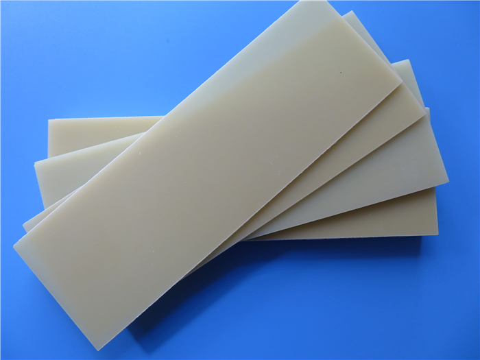
PTFE-Based Laminates (e.g., Rogers RT/duroid, Taconic TLY)
PTFE (polytetrafluoroethylene) is the gold standard for ultra-high-frequency applications. It offers the lowest dielectric loss among organic materials, with Df values as low as 0.0009 at 10 GHz.
Key characteristics:
Dielectric constant: 2.0–2.55, stable across frequency
Loss factor: ≤0.001
Temperature range: -200°C to 260°C
Typical applications: 77 GHz automotive radar, satellite communications, aerospace
Advantages: Ultra-low signal loss, stable electrical performance across temperature extremes, excellent chemical resistance.
Disadvantages: Expensive; poor adhesion to copper foil requiring specialized surface treatment; higher processing difficulty.
Ceramic-Filled Hydrocarbon Laminates (e.g., Rogers RO4000 Series)
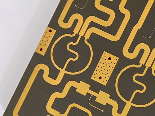
RO4000 series materials, particularly RO4350B laminate, represent a popular balance between high-frequency performance and manufacturability. They are designed to be processed using standard FR-4 fabrication methods, reducing production costs.
Key characteristics:
Dielectric constant: 3.48±0.05 at 10 GHz
Loss factor: 0.0037 at 10 GHz
Typical applications: 5G base stations (<24 GHz), automotive radar, power amplifiers
Advantages: Good high-frequency performance with FR-4 process compatibility; cost-effective for high-volume production.
Disadvantages: Higher thermal expansion in Z-axis; not suitable for millimeter-wave applications above 30 GHz.
Modified Epoxy / Low-Loss Thermoplastics (e.g., Panasonic Megtron)
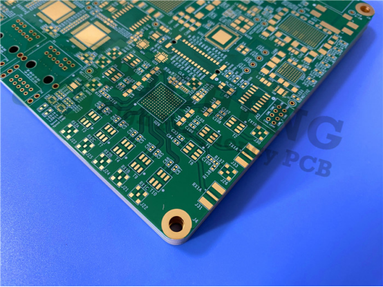
Materials like Megtron 6 and 7 are designed for high-speed digital applications where signal integrity at multi-gigabit speeds is critical. They offer lower loss than standard FR-4 while maintaining reasonable processing costs.
Key characteristics:
Dielectric constant: 3.3–3.6
Loss factor: 0.0015–0.0025
Typical applications: High-speed servers, data centers, high-speed digital backplanes
Advantages: Balanced performance for high-speed digital; good cost-to-performance ratio.
Disadvantages: Not ideal for extreme millimeter-wave frequencies above 60 GHz.
Liquid Crystal Polymer (LCP)
LCP is an emerging material for flexible and rigid-flex high-frequency applications. It combines low loss with excellent thermal stability and unique flexibility properties.
Key characteristics:
Dielectric constant: 2.6–3.1
Loss factor: <0.002
Typical applications: 5G millimeter-wave, wearable devices, flexible circuits
Advantages: Low signal loss, excellent thermal stability (>200°C), flexible form factor, good chemical resistance.
Disadvantages: Higher cost; specialized processing required
Material Family |
Dk (@10GHz) |
Df (@10GHz) |
Key Applications |
Cost |
Processing |
Rogers RT/duroid 5880 (PTFE) |
2.20±0.02 |
0.0009 |
Millimeter-wave, satellite, 77GHz radar |
Very High |
Specialized |
Taconic TLY-5 (PTFE) |
2.33 |
0.0009 |
Automotive radar, aerospace |
High |
Specialized |
Rogers RO4350B (Ceramic-filled) |
3.48±0.05 |
0.0037 |
5G base stations, <30GHz applications |
Moderate |
FR-4 compatible |
Isola I-Tera MT40 |
3.45±0.05 |
0.0031 |
High-speed backplanes |
Moderate |
FR-4 compatible |
Panasonic Megtron 6 |
3.6±0.1 |
0.0025 |
High-speed servers, data centers |
Moderate |
Standard |
FR-4 (Reference) |
4.2–4.8 |
0.018–0.025 |
Consumer electronics, <1GHz |
Low |
Standard |
3.Specialized Manufacturing for High-Frequency PCBs
High-frequency materials demand manufacturing processes that differ significantly from standard FR-4 production. Even a perfect laminate will underperform if not processed correctly.
Material-Specific Challenges
PTFE-based materials present particular difficulties: they are soft, prone to dimensional movement during processing, and have poor copper adhesion. Fabricators must use plasma treatment or special chemical etching to prepare surfaces for copper bonding. Drilling requires specialized parameters to avoid rough hole walls that cause signal reflections.
Ceramic-filled materials like RO4350B are more forgiving but still require careful impedance control. The ceramic content makes them harder and more abrasive on tooling, requiring frequent replacement of drill bits.
Critical Process Considerations
Lamination: For mixed-dielectric constructions (e.g., Rogers cores with FR-4 prepreg), the thermal expansion coefficients must be matched to prevent warping or delamination. Pressure and temperature profiles must be precisely controlled to avoid voids that degrade electrical performance.
Impedance Control: With tighter tolerances than standard boards, high-frequency PCB fabrication relies on TDR (time-domain reflectometry) testing and real-time calibration. HFSS electromagnetic simulation is often used pre-production to ensure impedance matches design targets.
Surface Finish Selection: While ENIG is common, high-frequency circuits often prefer silver or gold plating for optimal conductivity. OSP (organic solderability preservative) is generally avoided due to its limited shelf life and higher loss. For 77 GHz applications, copper foil roughness must be below 1μm RMS to minimize skin effect losses.
Advanced Techniques
Back-drilling: Removes unused stubs from plated through-holes, eliminating signal reflections at high frequencies.
LDI (Laser Direct Imaging): Provides high-resolution imaging for fine lines and spaces, essential for millimeter-wave circuit patterns.
Mixed-dielectric construction: Combines PTFE cores with FR-4 outer layers to balance signal performance with structural strength and cost.
4.Final Thoughts
Selecting a high-frequency PCB material requires a careful evaluation of performance requirements, budget constraints, and manufacturing capabilities. For applications below 24 GHz with cost sensitivity, ceramic-filled materials like RO4350B offer an excellent balance. For millimeter-wave radar or satellite communications, PTFE-based laminates such as RT/duroid or TLY-5 are essentially mandatory.
Equally important is choosing a fabricator with proven experience processing these materials. The unique challenges of PTFE bonding, impedance control, and mixed-dielectric lamination demand specialized equipment and process knowledge.
Need a PCB partner who understands the complexities of high-frequency materials? Bicheng PCB offers a full range of high-frequency laminates and finished PCBs, with proven experience in Rogers, Taconic, and other advanced materials. From 5G base stations to automotive radar, we deliver boards that meet the most demanding signal integrity requirements. [Contact us] to discuss your high-frequency project.