


 Home
-
Newly shipped PCBs
-
Rogers RT/Duroid 5880 Double-Layer Immersion Gold PCB 31mil 5880 Circuit Board for Millimeter Wave and Military Radar Applications
Home
-
Newly shipped PCBs
-
Rogers RT/Duroid 5880 Double-Layer Immersion Gold PCB 31mil 5880 Circuit Board for Millimeter Wave and Military Radar Applications
Rogers RT/Duroid 5880 Double-Layer Immersion Gold PCB 31mil 5880 Circuit Board for Millimeter Wave and Military Radar Applications
Printed Circuit Boards are custom-made products; the images and specifications provided are for reference only.
1. Introduction of Rogers RT/Duroid 5880 PCB
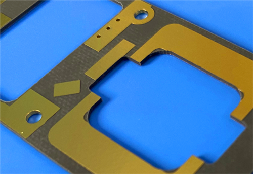
Rogers RT/Duroid 5880 PCB is a premium low-loss high-frequency rigid circuit board tailored for high-precision RF and millimeter-wave circuit designs. This Rogers 2-Layer PCB adopts authentic Rogers RT/Duroid 5880 glass microfiber reinforced PTFE composite laminate, a industry-leading dielectric material well-known for ultra-stable electrical performance. Featuring randomly oriented microfiber structure, Rogers RT/Duroid 5880 substrate delivers exceptional dielectric constant uniformity across the entire panel and maintains consistent parameters over an extremely wide frequency spectrum.
Manufactured with 0.85mm finished board thickness and 31mil (0.787mm) core dielectric thickness, RT/Duroid 5880 2-Layer high-frequency PCB applies Immersion Gold surface finish to ensure superior solderability and long-term surface stability. Produced in accordance with IPC-Class-2 industrial standards and 100% electrically tested before delivery, Rogers 5880 PCB provides reliable, low-signal-loss performance for military radar, millimeter-wave devices, broadband antenna systems and high-end microwave circuit projects worldwide.
2. Key Features of Rogers RT/Duroid 5880 PCB
- Adopts Rogers RT/Duroid 5880 glass microfiber reinforced PTFE composite substrate with ultra-uniform electrical performance
- Extremely stable dielectric constant (Dk): 2.2 ± 0.02 at 10 GHz with consistent panel-to-panel uniformity
- Ultra-low dissipation factor ranging from 0.0004 to 0.0009 at 10 GHz, delivering the lowest electrical loss among reinforced PTFE materials
- Ultra-low moisture absorption rate of 0.02%, preventing electrical parameter drift in humid environments
- Excellent isotropic material properties for balanced electrical performance in all directions
- Superior chemical resistance to adapt to diverse PCB manufacturing processes and complex application environments
- UL 94V-0 flammability rating for enhanced operational safety
- Fully compatible with lead-free manufacturing processes to meet modern environmental and industrial standards
- Blind-via-free design simplifies circuit structure and improves production stability
- Standard 1oz copper weight and 20μm via plating thickness ensure stable conductivity and structural durability
3. Product Benefits
- Ultra-Low High-Frequency Signal Loss: As the lowest-loss reinforced PTFE PCB material, RT/Duroid 5880 drastically minimizes signal attenuation, supporting stable transmission for Ku-band and even higher millimeter-wave frequency applications
- Full-Band Electrical Consistency: Uniform dielectric constant across wide frequency ranges and entire board panels eliminates impedance deviation, ensuring precise microstrip and stripline circuit performance
- Superior Environmental Stability: Near-zero moisture absorption and excellent chemical resistance maintain stable electrical and mechanical properties under variable temperature and humidity conditions
- Reliable Isotropic Performance: Balanced isotropic characteristics deliver uniform signal transmission in all directions, ideal for high-precision radar and antenna circuit design
- High Safety & Process Compatibility: UL 94V-0 flame retardant grade and lead-free process adaptability support standardized, safe, and eco-friendly mass production
- Strict Quality Assurance: 100% pre-shipment electrical testing eliminates defective products, guaranteeing consistent batch quality for high-end military and commercial RF projects
4. PCB Construction Details
Parameter Item |
Specification Details |
Base Material |
Rogers RT/Duroid 5880 |
Layer Count |
2-Layer |
Board Dimensions |
102mm x 65mm (1PCS), Tolerance: +/- 0.15mm |
Minimum Trace/Space |
4/6 mils |
Minimum Hole Size |
0.35mm |
Blind Vias Design |
No Blind Vias |
Finished Board Thickness |
0.85mm |
Finished Cu Weight |
1oz (1.4 mils) |
Via Plating Thickness |
20 μm |
Surface Finish |
Immersion Gold |
Top Silkscreen |
No |
Bottom Silkscreen |
No |
Top Solder Mask |
No |
Bottom Solder Mask |
No |
Pre-Shipment Test |
100% Electrical Test Prior to Shipment |
5. PCB Stackup
This 2-Layer rigid Rogers RT/Duroid 5880 PCB adopts a symmetrical and standardized stackup structure with uniform material distribution, ensuring ultra-stable electrical performance for high-frequency and millimeter-wave circuits:
- Copper Layer 1: 35 μm Finished Copper
- RT/Duroid 5880 Dielectric: 31mil (0.787mm)
- Copper Layer 2: 35 μm Finished Copper
6. PCB Statistics
- Total Components: 46
- Total Pads: 53
- Thru Hole Pads: 28
- Top SMT Pads: 25
- Bottom SMT Pads: 0
- Total Vias: 29
- Total Nets: 2
7. Artwork & Production Standard
- Supplied Artwork Type: Gerber RS-274-X
- Manufacturing Compliance Standard: IPC-Class-2
- Product Supply Scope: Worldwide Availability
8. Typical PCB Applications
- Commercial Airline Broadband Antennas
- High-Precision Microstrip and Stripline Circuits
- Advanced Millimeter Wave Devices & Systems
- Military Radar Systems
- Missile Guidance Systems
- Point-to-Point Digital Radio Antennas
9. Rogers RT/Duroid 5880 Copper Clad Laminate (CCL) Introduction
Rogers RT/Duroid 5880 is a high-end glass microfiber reinforced PTFE copper clad laminate developed for ultra-precise stripline and microstrip high-frequency circuit applications. Different from traditional woven glass substrates, RT/Duroid 5880 high-frequency laminate adopts a unique randomly oriented microfiber structure, which effectively eliminates electrical performance deviations and achieves exceptional dielectric constant uniformity across the entire laminate panel.
This professional RF laminate features stable and consistent Dk values panel by panel, with zero parameter drift over a wide frequency range. Its ultra-low dissipation factor enables reliable and low-loss signal transmission even at Ku-band and millimeter-wave frequencies, far exceeding the performance limits of ordinary high-frequency substrates. Benefiting from low moisture absorption, excellent chemical resistance and isotropic material characteristics, RT/Duroid 5880 laminate maintains stable electrical and mechanical properties in complex and harsh working environments.
With UL 94V-0 flame retardant certification and full lead-free process compatibility, RT/Duroid 5880 copper clad laminate supports modern standardized PCB fabrication. It is the optimal core substrate for manufacturing high-end commercial communication antennas, millimeter-wave circuits and military radar system PCBs, widely recognized for its ultra-reliable high-frequency performance in global aerospace and communication industries.
 RTduroid 5880.jpg)
9.1 Core Features of RT/Duroid 5880 Laminate
- Ultra-low electrical loss, ranking the best among all reinforced PTFE dielectric materials
- Extremely low moisture absorption avoids environmental interference on electrical performance
- Superior isotropic properties ensure balanced signal transmission in all directions
- Full-band uniform electrical properties suitable for wide-spectrum high-frequency designs
- Outstanding chemical resistance adapts to various PCB processing chemicals
- Stable Dk 2.2 dielectric constant with ultra-tight tolerance at 10 GHz
- UL 94V-0 flame retardant grade for high-safety industrial applications
- Compatible with lead-free PCB manufacturing processes
9.2 Main RT/Duroid 5880 Application Scenarios
- Commercial Aviation Broadband Antenna Systems
- Precision Microstrip & Stripline Microwave Circuits
- Millimeter Wave Communication & Detection Devices
- Military-Grade Radar & Missile Guidance Systems
- Long-Distance Point-to-Point Digital Radio Antennas
- 10.Datasheet
PROPERTY |
TYPICAL VALUES |
DIRECTION |
UNITS |
CONDITION |
TEST METHOD |
Dielectric Constant, εr (Process) |
2.202.20 ± 0.02 spec. |
Z |
N/A |
C24/23/501 MHz10 GHz |
IPC-TM-650 2.5.5.3IPC-TM-650 2.5.5.5 |
Dielectric Constant, εr (Design) |
2.20 |
Z |
N/A |
8 GHz - 40 GHz |
Differential Phase Length Method |
Dissipation Factor, tan δ |
0.00040.0009 |
Z |
N/A |
C24/23/501 MHz10 GHz |
IPC-TM-650 2.5.5.3IPC-TM-650 2.5.5.5 |
Thermal Coefficient of εr |
-125 |
Z |
ppm/°C |
-50 ~ 150°C |
IPC-TM-650 2.5.5.5 |
Volume Resistivity |
2 × 10⁷ |
Z |
Mohm·cm |
C96/35/90 |
ASTM D257 |
Surface Resistivity |
3 × 10⁷ |
Z |
Mohm |
C96/35/90 |
ASTM D257 |
Specific Heat |
0.96 (0.23) |
N/A |
J/g/K (cal/g/°C) |
N/A |
Calculated |
Tensile Modulus(23 °C / 100 °C) |
1070 (156) / 450 (65)860 (125) / 380 (55) |
XY |
MPa (kpsi) |
Test at 23 °C / 100 °C |
ASTM D638 |
Ultimate Tensile Stress(23 °C / 100 °C) |
29 (4.2) / 20 (2.9)27 (3.9) / 18 (2.6) |
XY |
MPa (kpsi) |
Test at 23 °C / 100 °C |
ASTM D638 |
Ultimate Tensile Strain(23 °C / 100 °C) |
6.0 / 7.24.9 / 5.8 |
XY |
% |
Test at 23 °C / 100 °C |
ASTM D638 |
Compressive Modulus(23 °C / 100 °C) |
710 (103) / 500 (73)710 (103) / 500 (73)940 (136) / 670 (97) |
XYZ |
MPa (kpsi) |
Test at 23 °C / 100 °C |
ASTM D695 |
Ultimate Compressive Stress(23 °C / 100 °C) |
27 (3.9) / 22 (3.2)29 (5.3) / 21 (3.1)52 (7.5) / 43 (6.3) |
XYZ |
MPa (kpsi) |
Test at 23 °C / 100 °C |
ASTM D695 |
Ultimate Compressive Strain(23 °C / 100 °C) |
8.5 / 8.47.7 / 7.812.5 / 17.6 |
XYZ |
% |
Test at 23 °C / 100 °C |
ASTM D695 |
Moisture Absorption |
0.02 |
N/A |
% |
0.062” (1.6mm), D48/50 |
ASTM D570 |
Thermal Conductivity |
0.20 |
Z |
W/m/K |
80°C |
ASTM C518 |
Coefficient of Thermal Expansion |
3148237 |
XYZ |
ppm/°C |
0~100°C |
IPC-TM-650 2.4.41 |
Td |
500 |
N/A |
°C |
TGA |
ASTM D3850 |
Density |
2.2 |
N/A |
gm/cm³ |
N/A |
ASTM D792 |
Copper Peel Strength |
31.2 (5.5) |
N/A |
pli (N/mm) |
1 oz (35μm) EDC foil, after solder float |
IPC-TM-650 2.4.8 |
Flammability |
V-0 |
N/A |
N/A |
N/A |
UL94 |
Lead-Free Process Compatible |
Yes |
N/A |
N/A |
N/A |
N/A |
11. Product Summary
Rogers RT/Duroid 5880 2-Layer high frequency PCB is an ultra-low-loss high-performance circuit board designed for millimeter-wave, military radar and broadband antenna applications. Built with premium 31mil RT/Duroid 5880 microfiber-reinforced PTFE substrate and 0.85mm finished thickness, 5880 2-Layer PCB adopts Immersion Gold surface treatment and complies with strict IPC-Class-2 manufacturing standards. Rogers 5880 RF circuit board features industry-leading low dissipation factor, full-band uniform Dk stability, ultra-low moisture absorption and excellent isotropic performance, effectively reducing high-frequency signal loss and ensuring precise circuit operation. With reliable environmental adaptability and standardized production compatibility, Rogers RT/Duroid 5880 PCB Board serves high-precision commercial communication and military microwave systems, providing stable and durable high-frequency circuit solutions for global customers.
Tags:Rogers RT/Duroid 5880 PCB, RT/Duroid 5880 2-Layer PCB, 0.85mm Millimeter Wave PCB, 31mil RT5880 Laminate, Immersion Gold RF PCB, Rogers 5880 Circuit Board, Dk 2.2 Microwave PCB, IPC-Class-2 Rigid PCB, Military Radar PCB, Missile Guidance PCB, Aviation Broadband Antenna PCB, Point To Point Digital Radio PCB, Microstrip Stripline Circuit PCB, UL 94V-0 High Frequency PCB