


 Home
-
Newly shipped PCBs
-
40mil TFA294 Double-sided Low Loss PCB with Immersion Gold for Aerospace, Radar and Satellite Communication
Home
-
Newly shipped PCBs
-
40mil TFA294 Double-sided Low Loss PCB with Immersion Gold for Aerospace, Radar and Satellite Communication
40mil TFA294 Double-sided Low Loss PCB with Immersion Gold for Aerospace, Radar and Satellite Communication
Printed Circuit Boards are custom-made products; the images and specifications provided are for reference only.
1. Introduction of TFA294 PCB
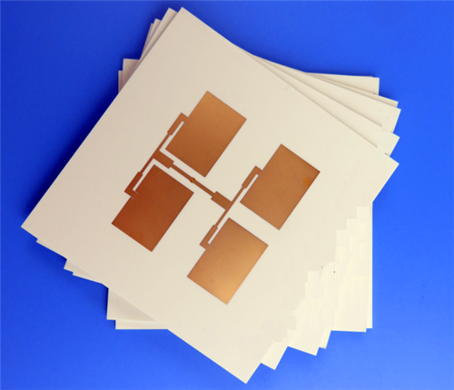
TFA294 PCB is a high-reliability aerospace-grade high-frequency rigid circuit board built with advanced TFA-series PTFE ceramic composite dielectric substrate. Different from traditional high-frequency substrates that adopt glass fiber cloth impregnation processes, the TFA294 dielectric core is manufactured through a innovative prefabrication and special lamination technology, without adding glass fiber cloth inside the material structure. This unique production process eliminates the common fiberglass effect during electromagnetic wave transmission, delivering purer and more stable high-frequency signal performance.
As one of the core models of the TFA substrate series, TFA294 laminate features a fixed dielectric constant of 2.94 and supports multi-band stable operation from 10 GHz to 40 GHz. The material adopts uniform nano-ceramic and PTFE resin mixing formula, which greatly reduces X/Y/Z axis anisotropy and achieves a low thermal expansion coefficient close to copper foil. This 2-Layer PCB is fabricated with a 40mil core substrate thickness and 1.1mm finished board thickness, paired with Immersion Gold surface finish. Compliant with IPC-Class-2 quality standards and 100% electrically tested before shipment, TFA294 PCB provides consistent, low-loss and thermally stable circuit performance for aerospace, radar, satellite communication and high-end antenna systems worldwide.
2. Key Features of TFA294 PCB
- Adopts professional TFA294 PTFE ceramic composite substrate without glass fiber cloth structure
- Stable dielectric constant (Dk): 2.94 at 10 GHz with excellent frequency consistency
- Ultra-low dissipation factor: 0.0010 at 10 GHz & 20 GHz, 0.0012 at 40 GHz for minimal high-frequency signal loss
- Low TCDK value of -5 ppm/°C within the temperature range of -55°C to 150°C, ensuring stable dielectric performance under temperature fluctuation
- Precise thermal expansion coefficients: 18 ppm/°C (X-axis), 18 ppm/°C (Y-axis), 32 ppm/°C (Z-axis) from -55°C to 288°C
- Reliable thermal conductivity of 0.59 W/mk for efficient heat dissipation
- Ultra-low moisture absorption rate of 0.03% to avoid electrical parameter drift in humid environments
- UL 94-V0 flammability rating, meeting high-standard safety requirements for aerospace equipment
- Blind-via-free design, simplifying circuit structure and improving production consistency
- Standard 1oz outer copper weight and 20μm via plating thickness for stable conductivity and structural durability
3. Product Benefits
- Eliminate Fiberglass Interference: Glass-free substrate structure completely removes the fiberglass effect during electromagnetic wave propagation, ensuring pure and accurate high-frequency signal transmission
- Ultra-Stable Wide-Band Performance: Extremely low dissipation factor across 10GHz to 40GHz bands and low TCDK realize consistent electrical performance in variable temperature and high-frequency working conditions
- Minimal Material Anisotropy: Balanced X/Y-axis CTE and low Z-axis expansion reduce structural deformation and impedance deviation, improving circuit precision and stability
- Excellent Thermal Management: Reliable thermal conductivity efficiently dissipates operating heat, extending service life of high-power and high-frequency circuit systems
- Superior Environmental Adaptability: Low moisture absorption and stable temperature resistance maintain long-term performance stability in complex aerospace and outdoor working environments
- Aerospace-Grade Safety & Reliability: UL 94-V0 flame retardant performance and innovative composite material technology support high-reliability applications in aviation, space and military radar equipment
- High Batch Consistency: Mature integrated lamination process ensures uniform substrate performance, supporting mass production of high-precision high-frequency PCBs
4. PCB Construction Details
Parameter Item |
Specification Details |
Base Material |
TFA294 PTFE Ceramic Composite Substrate |
Layer Count |
2-Layer |
Board Dimensions |
97.53mm x 100.28mm (1PCS), Tolerance: +/- 0.15mm |
Minimum Trace/Space |
4/6 mils |
Minimum Hole Size |
0.35mm |
Blind Vias Design |
No Blind Vias |
Finished Board Thickness |
1.1mm |
Finished Cu Weight |
1oz (1.4 mils) Outer Layers |
Via Plating Thickness |
20 μm |
Surface Finish |
Immersion Gold |
Top Silkscreen |
No |
Bottom Silkscreen |
No |
Top Solder Mask |
No |
Bottom Solder Mask |
No |
Pre-Shipment Test |
100% Electrical Test Prior to Shipment |
5. PCB Stackup
This 2-Layer rigid TFA294 PCB adopts a stable symmetrical stackup structure with 40mil high-performance ceramic composite core material, delivering uniform electrical and thermal performance for high-frequency aerospace circuit systems:
- Copper Layer 1: 35 μm Finished Copper
- TFA294 Core Substrate: 40mil (1.016mm)
- Copper Layer 2: 35 μm Finished Copper
6. PCB Statistics
- Total Components: 21
- Total Pads: 32
- Thru Hole Pads: 18
- Top SMT Pads: 14
- Bottom SMT Pads: 0
- Total Vias: 13
- Total Nets: 2
7. Artwork & Production Standard
- Supplied Artwork Type: Gerber RS-274-X
- Manufacturing Quality Standard: IPC-Class-2
- Product Supply Scope: Worldwide Availability
8. Typical PCB Applications
- Aerospace Equipment and Space In-Cabin Electronic Devices
- Aircraft and Aviation Supporting Electronic Systems
- High-Frequency Microwave Devices and Antenna Systems
- Phase-Sensitive Antennas and Phased Array Antenna Equipment
- Beamforming Network Circuit Modules
- Early Warning Radar and Airborne Radar Systems
- Satellite Communication and Navigation Equipment
- RF Microwave Power Amplifiers
9. TFA & TFA294 Copper Clad Laminate Introduction
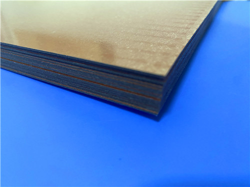
The TFA series represents a professional aerospace-grade PTFE ceramic composite dielectric copper clad laminate lineup, independently engineered as a high-reliability alternative to imported premium high-frequency substrate materials. Different from conventional high-frequency laminates that rely on fiberglass cloth impregnation for pre-preg manufacturing, the TFA series adopts an innovative production process: specialized nano-ceramic powder is uniformly blended with high-purity PTFE resin to form prefabricated sheets, followed by precision customized lamination pressing. This unique fiberglass-free structural design eliminates the traditional fiberglass effect during electromagnetic wave transmission, laying a solid foundation for ultra-stable high-frequency performance.
As a core model of the TFA substrate family, TFA294 CCL inherits all superior properties of the series. The fiberglass-free composite structure minimizes X/Y/Z-axis material anisotropy, delivering industry-leading low dielectric loss and exceptional frequency stability among equivalent Dk-level materials. It features a thermal expansion coefficient highly matched with copper foil and steady dielectric temperature characteristics across extreme temperature ranges. The TFA series offers four customizable dielectric constant specifications: Dk 2.94 (TFA294), Dk 3.0 (TFA300), Dk 6.15 (TFA615), and Dk 10.2 (TFA1020), meeting diverse design demands for different high-frequency circuit scenarios.
In terms of copper foil configuration and structural flexibility, TFA-series laminates are standard-equipped with low-roughness RTF copper foil, which effectively reduces conductor loss while maintaining excellent peel strength. For customized requirements, the substrates support rolled copper foil lamination, and are compatible with copper-based and aluminum-based composite structures. Notably, TFA294 and TFA300 can be paired with embedded 50Ω resistance copper foil to form integrated resistance film substrates, realizing highly integrated circuit design and simplifying PCB structural layout.
In terms of process adaptability, TFA294 and full TFA-series CCL support standard PTFE board fabrication processes. Thanks to outstanding mechanical rigidity and stable physical properties, these laminates excel in multi-layer, high-layer-count and backplane PCB processing. They also deliver superior machinability for dense via holes and fine trace circuits, fully adapting to high-precision industrial and aerospace PCB manufacturing standards.
9.1 Core Features of TFA Series & TFA294 CCL
- Tight Dielectric Constant Tolerance & Excellent Batch Consistency: TFA294 substrates maintain ultra-precise Dk 2.94 parameters with minimal deviation between production batches, ensuring uniform electrical performance for mass-produced high-frequency PCBs.
- Ultra-Low Dielectric Loss at Equivalent Dk Level: Optimized nano-ceramic and PTFE composite formula achieves minimal signal attenuation, supporting ultra-stable high-frequency signal transmission.
- Super Wide Frequency Application Range: Rated for operating frequencies up to 77GHz, fully covering millimeter-wave frequency bands and meeting technical requirements for automotive radar, microwave communication and high-precision RF devices.
- Extreme Temperature Frequency & Phase Stability: Maintains consistent dielectric performance, frequency stability and phase stability throughout the wide temperature range of -55°C to 150°C, adapting to harsh temperature fluctuation environments.
- Excellent Radiation Resistance: Retains stable dielectric and physical properties after high-dose radiation exposure, making it qualified for aerospace and space-level extreme working conditions.
- Low Outgassing Performance: Complies with aerospace vacuum outgassing standards via professional vacuum volatility testing, suitable for space cabin and aerospace vacuum equipment applications.
- Copper-Foil-Matched Thermal Expansion Coefficient: Low CTE performance perfectly matches copper foil expansion characteristics, ensuring reliable plated through-hole quality and long-term dimensional thermal stability.
- Ultra-Low Water Absorption: Effectively prevents electrical parameter drift caused by humid environments, maintaining stable circuit performance in complex atmospheric conditions.
9.2 Processing & Structural Advantages of TFA294 CCL
- Fiberglass-free structure eliminates electromagnetic interference and signal distortion during high-frequency transmission
- Compatible with standard PTFE PCB processing techniques for cost-effective and efficient manufacturing
- Supports multi-layer, high-layer-count and backplane PCB fabrication with excellent structural stability
- Superior machinability for dense via holes and fine trace circuits, suitable for high-precision miniaturized circuits
- Flexible copper foil matching: standard RTF low-roughness copper, optional rolled copper, copper base and aluminum base composite structures
- Customizable resistance film structure with embedded 50Ω resistance copper foil for TFA294 models
9.3 Main Application Scenarios of TFA294 CCL
- Aerospace & Aviation: Space equipment, aircraft in-cabin electronic devices and aviation supporting systems
- High-Frequency Microwave Systems: Microwave circuits, high-precision antennas and phase-sensitive antenna equipment
- Radar Systems: Early warning radar, airborne radar and various military and civil radar detection devices
- Array Antenna Systems: Phased array antennas and high-precision beamforming network modules
- Satellite Systems: Satellite communication, navigation positioning and space communication equipment
- RF Microwave Devices: High-frequency power amplifiers and millimeter-wave core components
TFA294 is a premium glass-free PTFE ceramic composite copper clad laminate belonging to the high-reliability TFA substrate series, specially developed for aerospace and high-end military high-frequency PCB manufacturing. Breaking the traditional glass fiber cloth impregnation production process, TFA-series substrates adopt nano-ceramic and PTFE resin uniform mixing formula, paired with customized prefabrication and special lamination molding technology, effectively avoiding signal distortion caused by glass fiber structure in traditional high-frequency materials.
This glass-free composite design eliminates the fiberglass effect during electromagnetic wave transmission, achieving extremely stable frequency performance and ultra-low dielectric loss across broadband frequencies. The material minimizes X/Y/Z axis anisotropy and features a low thermal expansion coefficient matching copper foil, as well as stable dielectric temperature characteristics. The TFA series includes multiple Dk specifications covering 2.94, 3.0, 6.15 and 10.2, corresponding to TFA294, TFA300, TFA615 and TFA1020 models respectively, providing flexible material selection for different high-frequency circuit design requirements.
With reliable thermal conductivity, low moisture absorption and UL 94-V0 flame retardant properties, TFA294 CCL maintains stable electrical and mechanical performance under extreme temperature changes and harsh working environments. It is a mature aerospace-grade substrate that can replace imported equivalent products, widely used in high-precision radar, satellite communication and aviation electronic equipment.
10.Datasheet
Product Property |
Test Condition |
Unit |
Typical Value |
Dielectric Constant (Typical) |
10 GHz |
/ |
2.94 |
Dielectric Constant (Design) |
10 GHz |
/ |
2.94 |
Dielectric Constant Tolerance |
/ |
/ |
±0.04 |
Dissipation Factor (Typical) |
10 GHz |
/ |
0.001 |
Dissipation Factor (Typical) |
20 GHz |
/ |
0.001 |
Dissipation Factor (Typical) |
40 GHz |
/ |
0.0012 |
Thermal Coefficient of Dielectric Constant |
-55 °C ~ 150 °C |
ppm/°C |
-5 |
Copper Peel Strength |
1 oz RTF Foil |
N/mm |
> 1.6 |
Volume Resistivity |
Ambient Condition |
MΩ·cm |
≥ 5×10⁷ |
Surface Resistivity |
Ambient Condition |
MΩ |
≥ 5×10⁷ |
Dielectric Strength (Z-axis) |
5KW, 500V/s |
KV/mm |
> 35 |
Breakdown Voltage (XY-axis) |
5KW, 500V/s |
KV |
> 40 |
Coefficient of Thermal Expansion (X, Y-axis) |
-55 °C ~ 288 °C |
ppm/°C |
18, 18 |
Coefficient of Thermal Expansion (Z-axis) |
-55 °C ~ 288 °C |
ppm/°C |
32 |
Thermal Stress |
260 °C, 10s, 3 cycles |
/ |
No Delamination |
Water Absorption |
20±2 °C, 24h |
% |
0.03 |
Density |
Ambient Temperature |
g/cm³ |
2.14 |
Continuous Operating Temperature |
Temperature & Humidity Chamber |
°C |
-55 ~ +260 |
Thermal Conductivity (Z-axis) |
/ |
W/(m·K) |
0.59 |
Flammability |
/ |
UL-94 |
V-0 |
Td (Onset Temperature) |
/ |
°C |
498 |
Material Composition |
/ |
/ |
PTFE + Ceramic(A tiny amount of glass fabric will be added when dielectric thickness exceeds 1.5mm) |
11. Product Summary
TFA294 2-Layer high frequency PCB is an aerospace-grade low-loss high-reliability circuit board customized for high-precision microwave and radar system applications. Adopting 40mil glass-free TFA294 nano-ceramic PTFE composite substrate and 1.1mm finished board thickness, this 2-Layer PCB features Immersion Gold surface treatment and complies with IPC-Class-2 manufacturing standards. It eliminates traditional fiberglass signal interference, delivers ultra-stable Dk parameters, ultra-low broadband dielectric loss and excellent thermal stability, with minimal material anisotropy and reliable environmental adaptability. Suitable for aerospace equipment, airborne radar, phased array antennas and satellite communication systems, this high-performance TFA294 PCB provides stable and professional high-frequency circuit solutions for global high-end aviation and military electronic industries.
Tags: TFA294 PCB, 2-Layer High Frequency PCB, 1.1mm Aerospace PCB, 40mil TFA294 Laminate, Immersion Gold PCB, Glass-Free PTFE Ceramic PCB, Low Loss Radar PCB, Ultra Stable Dk 2.94 PCB, IPC-Class-2 Rigid PCB, UL 94-V0 High Reliability PCB, Aerospace Equipment PCB, Airborne Radar PCB, Phased Array Antenna PCB, Satellite Communication PCB, Microwave Power Amplifier PCB