

 Home
-
Newly shipped PCBs
-
Rogers RT/duroid 5870 2-Layer PCB 10mil Low Loss RF Laminate PCB with Electroless Nickel Immersion Gold for Radar and Millimeter Wave Use
Home
-
Newly shipped PCBs
-
Rogers RT/duroid 5870 2-Layer PCB 10mil Low Loss RF Laminate PCB with Electroless Nickel Immersion Gold for Radar and Millimeter Wave Use
Rogers RT/duroid 5870 2-Layer PCB 10mil Low Loss RF Laminate PCB with Electroless Nickel Immersion Gold for Radar and Millimeter Wave Use
Printed Circuit Boards are custom-made products; the images and specifications provided are for reference only.
1. Rogers RT/duroid 5870 2-Layer PCB Introduction
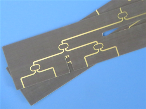
Rogers RT/duroid 5870 2-Layer High Frequency PCB is a high-precision rigid printed circuit board engineered with Rogers RT/duroid 5870 glass microfiber reinforced PTFE composite. This 0.3mm thick 2-layer PCB features a 10mil (0.254mm) RT/duroid 5870 core, characterized by exceptional dielectric constant uniformity thanks to randomly oriented microfibers. Equipped with Electroless Nickel Immersion Gold (ENIG) surface finish, precise dimensional control (±0.15mm), and full compliance with IPC-Class-2 standards, it delivers superior electrical performance with low loss, making it ideal for exacting stripline and microstrip circuit applications. Widely used in commercial airline broadband antennas, millimeter wave applications, radar systems, guidance systems, and point-to-point digital radio antennas, this PCB offers consistent reliability and stable electrical properties across a wide frequency range, even extending to Ku-band and above.
2. Rogers RT/duroid 5870 2-Layer PCB Features
- Dielectric Constant (Dk): 2.33 with tight tolerance of ±0.02 at 10 GHz
- Dissipation Factor (Df): 0.0012 at 10GHz, enabling low electrical loss even at high frequencies
- Temperature Coefficient of Dielectric Constant (TCDk): -115 ppm/°C
- Low Moisture Absorption: 0.02%, suitable for high moisture environments
- Coefficient of Thermal Expansion (CTE): X-axis 22 ppm/°C, Y-axis 28 ppm/°C, Z-axis 173 ppm/°C
- Isotropic properties, ensuring consistent performance across all directions
- Constructed with glass microfiber reinforced PTFE composite, balancing rigidity and processability
- Resistant to all solvents and reagents (hot or cold) used in PCB etching or plating processes
- Surface Finish: Electroless Nickel Immersion Gold (ENIG), ensuring excellent conductivity and corrosion resistance
3. Rogers RT/duroid 5870 2-Layer PCB Benefits
- Uniform electrical properties over a wide frequency range, ensuring consistent signal transmission
- Easily cut, sheared, and machined to shape, simplifying manufacturing and customization
- Strong resistance to solvents and reagents used in etching or plating edges and holes, reducing production damage
- Low moisture absorption (0.02%), making it ideal for high moisture environments
- Well-established material with proven reliability in high-frequency applications
- Lowest electrical loss among reinforced PTFE materials, extending usability to Ku-band and above
- ENIG surface finish provides superior solderability and long-term reliability
- Compatible with standard PCB manufacturing processes, no specialized techniques required
4. PCB Construction Details
Construction Item |
Specification |
Base Material |
Rogers RT/duroid 5870 |
Layer Count |
2 Layers |
Board Dimensions |
85mm x 36mm = 1PCS, +/- 0.15mm |
Minimum Trace/Space |
5/6 mils |
Minimum Hole Size |
0.4mm |
Blind Vias |
No |
Finished Board Thickness |
0.3mm |
Finished Cu Weight (Outer Layers) |
1 oz (1.4 mils) |
Via Plating Thickness |
20 μm |
Surface Finish |
Electroless Nickel Immersion Gold (ENIG) |
Top Silkscreen |
No |
Bottom Silkscreen |
No |
Top Solder Mask |
No |
Bottom Solder Mask |
No |
Pre-Shipment Electrical Test |
100% Electrical Test Used |
5. PCB Stackup
2-layer rigid PCB, with the following layer structure (from top to bottom):
- Copper_layer_1 - 35 μm
- Rogers RT/duroid 5870 Core - 0.254mm (10mil)
- Copper_layer_2 - 35 μm
6. PCB Statistics
- Components: 36
- Total Pads: 56
- Thru Hole Pads: 32
- Top SMT Pads: 24
- Bottom SMT Pads: 0
- Vias: 28
- Nets: 2
7. Artwork Format
Gerber RS-274-X, the industry-standard format for PCB fabrication, ensuring compatibility with most manufacturing equipment and processes worldwide.
8. Quality Standard
Complies with IPC-Class-2 standards, guaranteeing consistent quality, reliability, and performance for commercial, industrial, and high-tech applications.
9. Global Availability
Available worldwide, supported by reliable supply chains to meet global customers’ production needs and ensure timely delivery.
10. Typical Applications
- Commercial Airline Broadband Antennas
- Microstrip and Stripline Circuits
- Millimeter Wave Applications
- Radar Systems
- Guidance Systems
- Point to Point Digital Radio Antennas
11. Rogers RT/duroid 5870 CCL Introduction (Glass Microfiber Reinforced PTFE Composites)
Rogers RT/duroid® 5870 is a high-performance glass microfiber reinforced PTFE composite laminate, specifically designed for exacting stripline and microstrip circuit applications. The randomly oriented microfibers within the PTFE matrix deliver exceptional dielectric constant uniformity, ensuring consistent performance from panel to panel and across a wide frequency range. With its low dissipation factor, RT/duroid 5870 extends usability to Ku-band and above, making it a preferred choice for high-frequency RF and microwave systems.
 RTduroid 5870.jpg)
11.1 CCL Core Properties
- Glass microfiber reinforced PTFE composite structure, combining low loss and mechanical rigidity
- Dielectric Constant (Dk): 2.33 ± 0.02 at 10 GHz, with exceptional uniformity
- Dissipation Factor (Df): 0.0012 at 10GHz, offering the lowest electrical loss among reinforced PTFE materials
- Temperature Coefficient of Dielectric Constant (TCDk): -115 ppm/°C
- Low Moisture Absorption: 0.02%, suitable for high moisture environments
- CTE: X-axis 22 ppm/°C, Y-axis 28 ppm/°C, Z-axis 173 ppm/°C
- Isotropic properties, ensuring consistent performance in all directions
- Resistant to all solvents and reagents (hot or cold) used in PCB etching or plating processes
- Available with electrodeposited (EDC) copper (½ to 2 ounces/ft², 8 to 70μm), reverse treated EDC, rolled copper foil (for critical applications), or clad with aluminum, copper, or brass plates
11.2 CCL Key Advantages
- Lowest electrical loss for reinforced PTFE material, enabling high-performance at Ku-band and above
- Low moisture absorption, ensuring reliability in high humidity environments
- Isotropic properties, providing consistent electrical performance across all directions
- Uniform electrical properties over a wide frequency range, reducing performance variations
- Excellent chemical resistance, minimizing damage during fabrication and plating processes
- Easy processability—easily cut, sheared, and machined to shape without specialized equipment
- Versatile cladding options, adapting to diverse application requirements
- Well-established material with proven reliability in high-frequency industrial and aerospace applications
12.DataSheet
Property |
Typical Value |
Direction |
Unit |
Condition |
Test Method |
Electrical Properties |
|
|
|
|
|
Dielectric Constant (εr, Process) |
2.33 (2.33 ± 0.02 spec.) |
Z |
N/A |
C24/23/50, 1 MHz |
IPC-TM-650 2.5.5.3 |
|
2.33 |
Z |
N/A |
C24/23/50, 10 GHz |
IPC-TM-650 2.5.5.5 |
Dielectric Constant (εr, Design) |
2.33 |
Z |
N/A |
8 GHz – 40 GHz |
Differential Phase Length Method |
Dissipation Factor (tan δ) |
0.0005 |
Z |
N/A |
C24/23/50, 1 MHz |
IPC-TM-650 2.5.5.3 |
|
0.0012 |
Z |
N/A |
C24/23/50, 10 GHz |
IPC-TM-650 2.5.5.5 |
Thermal Coefficient of εr |
-115 |
Z |
ppm/°C |
-50 – 150°C |
IPC-TM-650 2.5.5.5 |
Volume Resistivity |
2×10⁷ |
Z |
MΩ·cm |
C96/35/90 |
ASTM D257 |
Surface Resistivity |
2×10⁷ |
Z |
MΩ |
C96/35/90 |
ASTM D257 |
Thermal Properties |
|
|
|
|
|
Specific Heat |
0.96 (0.23) |
N/A |
J/g/K (cal/g/°C) |
N/A |
Calculated |
Thermal Conductivity |
0.22 |
Z |
W/m/K |
80°C |
ASTM C518 |
CTE (0–100°C) |
22 |
X |
ppm/°C |
N/A |
IPC-TM-650 2.4.41 |
|
28 |
Y |
ppm/°C |
|
|
|
173 |
Z |
ppm/°C |
|
|
Decomposition Temperature (Td) |
500 |
N/A |
°C |
TGA |
ASTM D3850 |
Density |
2.2 |
N/A |
g/cm³ |
N/A |
ASTM D792 |
Mechanical Properties @ 23°C / @ 100°C |
|
|
|
|
|
Tensile Modulus |
1300 (189) / 490 (71) |
X |
MPa (kpsi) |
A |
ASTM D638 |
|
1280 (185) / 430 (63) |
Y |
MPa (kpsi) |
|
|
Ultimate Tensile Stress |
50 (7.3) / 34 (4.8) |
X |
MPa (kpsi) |
|
|
|
42 (6.1) / 34 (4.8) |
Y |
MPa (kpsi) |
|
|
Ultimate Tensile Strain |
9.8 / 8.7 |
X |
% |
|
|
|
9.8 / 8.6 |
Y |
% |
|
|
Compressive Modulus |
1210 (176) / 680 (99) |
X |
MPa (kpsi) |
A |
ASTM D695 |
|
1360 (198) / 860 (125) |
Y |
MPa (kpsi) |
|
|
|
803 (120) / 520 (76) |
Z |
MPa (kpsi) |
|
|
Ultimate Compressive Stress |
30 (4.4) / 23 (3.4) |
X |
MPa (kpsi) |
|
|
|
37 (5.3) / 25 (3.7) |
Y |
MPa (kpsi) |
|
|
|
54 (7.8) / 37 (5.3) |
Z |
MPa (kpsi) |
|
|
Ultimate Compressive Strain |
4.0 / 4.3 |
X |
% |
|
|
|
3.3 / 3.3 |
Y |
% |
|
|
|
8.7 / 8.5 |
Z |
% |
|
|
Copper Peel Strength |
27.2 (4.8) |
N/A |
pli (N/mm) |
1 oz (35 μm) EDC foil, after solder float |
IPC-TM-650 2.4.8 |
General Properties |
|
|
|
|
|
Moisture Absorption |
0.02 |
N/A |
% |
0.062” (1.6 mm), D48/50 |
ASTM D570 |
Flammability |
V-0 |
N/A |
N/A |
N/A |
UL 94 |
Lead-Free Process Compatible |
Yes |
N/A |
N/A |
N/A |
N/A |
13. Summary
Rogers 2-Layer RT/duroid 5870 High Frequency PCB is a high-precision, low-loss printed circuit board engineered for demanding high-frequency applications. Featuring a 0.3mm thickness (10mil RT/duroid 5870 core), 2-layer structure, and Electroless Nickel Immersion Gold surface finish, this PCB delivers exceptional dielectric uniformity, low electrical loss, and strong chemical resistance. Compliant with IPC-Class-2 standards and compatible with standard PCB manufacturing processes, it is an ideal solution for commercial airline broadband antennas, millimeter wave applications, radar systems, guidance systems, and point-to-point digital radio antennas. Globally available, it provides consistent quality and value for customers seeking reliable, high-performance RF and microwave PCB solutions.