


 Home
-
Newly shipped PCBs
-
Rogers DiClad 527 20mil Immersion Gold PCB Double-Layer Low Loss RF Microwave Printed Circuit Board
Home
-
Newly shipped PCBs
-
Rogers DiClad 527 20mil Immersion Gold PCB Double-Layer Low Loss RF Microwave Printed Circuit Board
Rogers DiClad 527 20mil Immersion Gold PCB Double-Layer Low Loss RF Microwave Printed Circuit Board
Printed Circuit Boards are custom-made products; the images and specifications provided are for reference only.
1. Introduction of Rogers DiClad 527 PCB
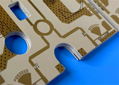
Rogers DiClad 527 2-layer PCB is a premium high-frequency printed circuit board engineered for rigorous RF and microwave electronic applications. Rogers rigid double-sided PCB adopts high-performance woven fiberglass reinforced PTFE composite substrate, featuring a scientifically optimized fiberglass-to-PTFE ratio that delivers stable dielectric performance and superior structural consistency. With a finished board thickness of 0.6mm, immersion gold surface treatment, and precise dimensional tolerance, Rogers DiClad 527 RF circuit board ensures reliable high-frequency signal transmission, excellent dimensional stability, and minimal performance fluctuation in complex and high-humidity working environments. Manufactured in compliance with IPC-Class-2 industry standards and 100% electrically tested before delivery, it provides consistent, low-loss circuit performance for commercial and industrial high-frequency electronic systems worldwide.
2. Key Features of DiClad 527 PCB
- Stable dielectric constant (Dk) ranging from 2.4 to 2.6 at 10 GHz and 1 MHz under 50% RH condition
- Ultra-low dissipation factor of 0.0017 at 10 GHz and 0.0010 at 1 MHz with 50% relative humidity
- Low TcDK value of -153 ppm/°C within the temperature range of -10°C to 140°C at 10 GHz, ensuring stable electrical performance under temperature changes
- Extremely low moisture absorption rate of 0.03%, resisting performance degradation caused by humid environments
- Precise and stable CTE parameters: 14 ppm/°C (X-axis), 21 ppm/°C (Y-axis), and 173 ppm/°C (Z-axis)
- Adopts 1oz outer layer copper weight and 20μm via plating thickness for reliable circuit conductivity and durability
- Precise manufacturing specifications with 4/6 mils minimum trace/space and 0.3mm minimum hole size, supporting fine-line circuit design
- No blind vias design, simplified circuit structure and improved production stability
- Black top silkscreen and no solder mask on both sides, meeting special high-frequency circuit design requirements
- 100% electrical testing implemented prior to shipment to guarantee product qualification rate
3. Product Benefits
- Extremely Low Loss Tangent: Effectively reduces high-frequency signal attenuation, ensuring efficient and accurate signal transmission for RF and microwave circuits
- Excellent Dimensional Stability: Optimized fiberglass and PTFE composite structure minimizes board deformation and size deviation during production and operation
- Consistent Product Performance Uniformity: Uniform substrate material properties ensure stable overall performance of each finished PCB board
- Highly Uniform Electrical Properties Across Frequencies: Maintains consistent electrical characteristics in wide frequency bands, adapting to multi-scene high-frequency application requirements
- Reliable Consistent Mechanical Performance: Stable CTE parameters enhance the PCB’s adaptability to temperature changes and mechanical stress
- Superior Excellent Chemical Resistance: Resists corrosion from common industrial chemicals, extending product service life
- Stable Dk Over Wide Frequency Range: Avoids dielectric constant drift in different frequency environments, ensuring stable circuit impedance matching
- Low Circuit Loss at High Frequency: Greatly improves the working efficiency of high-frequency electronic equipment and reduces energy consumption
- Negligible Humidity-Induced Performance Drift: Low moisture absorption ensures stable working performance in high-humidity and harsh outdoor environments
4. PCB Construction Details
Parameter Item |
Specification Details |
Base Material |
DiClad 527 |
Layer Count |
2-layer rigid PCB |
Board Dimensions |
49.63mm x 91.54mm (1PCS), Tolerance: +/- 0.15mm |
Minimum Trace/Space |
4/6 mils |
Minimum Hole Size |
0.3mm |
Blind Vias Design |
No Blind Vias |
Finished Board Thickness |
0.6mm |
Finished Cu Weight (Outer Layers) |
1oz (1.4 mils) |
Via Plating Thickness |
20 μm |
Surface Finish |
Immersion Gold |
Top Silkscreen |
Black |
Bottom Silkscreen |
No |
Top Solder Mask |
No |
Bottom Solder Mask |
No |
Pre-Shipment Test |
100% Electrical Test |
5. PCB Stackup
This 2-layer rigid Rogers DiClad 527 PCB adopts a standard symmetrical stackup structure with stable thickness and uniform material distribution, ensuring excellent high-frequency performance:
- Copper_layer_1: 35 μm
- DiClad 527 Substrate: 0.508 mm (20mil)
- Copper_layer_2: 35 μm
6. PCB Statistics
- Components: 36
- Total Pads: 104
- Thru Hole Pads: 63
- Top SMT Pads: 41
- Bottom SMT Pads: 0
- Vias: 19
- Nets: 2
7. Artwork & Production Standard
- Type of Artwork Supplied: Gerber RS-274-X
- Accepted Manufacturing Standard: IPC-Class-2
- Product Availability: Worldwide Supply & Service
8. Typical PCB Applications
- Radar Feed Networks
- Commercial Phased Array Networks
- Low Loss Base Station Antennas
- Guidance Systems
- Digital Radio Antennas
- High-frequency Filters, Couplers, LNAs (Low Noise Amplifiers)
9. DiClad 527 Copper Clad Laminate (CCL) Introduction
Rogers DiClad® 527 belongs to the premium PTFE woven fiberglass reinforced copper clad laminate series, which is professionally developed as a high-performance substrate for high-frequency printed circuit boards. Different from ordinary non-woven fiberglass PTFE laminates, Rogers DiClad 527 Laminate adopts a precisely calibrated woven fiberglass and PTFE composite formula, with a controllable material ratio that balances outstanding electrical performance and rigid mechanical properties for high-frequency PCB manufacturing.
The core advantage of DiClad® series copper clad laminates lies in its standardized woven fiberglass structure and uniform PTFE coating process. All fiberglass plies are arranged in a consistent direction, and optional cross-plied specifications are available for customized CuClad laminate solutions. This sophisticated manufacturing process delivers far better dielectric constant uniformity and dimensional stability than conventional non-woven fiberglass reinforced substrates, effectively eliminating performance deviations caused by material inconsistencies.
DiClad 527 copper clad laminate features a relatively high fiberglass-to-PTFE ratio. This unique formula enables the laminate to achieve mechanical properties comparable to traditional rigid PCB substrates, while maintaining ultra-low high-frequency loss characteristics. It boasts lower thermal expansion coefficients in all axes and superior structural stability. Its electrical performance is strictly tested at 1 MHz low frequency and 10 GHz high frequency, with a stable dielectric constant (Er) range of 2.40 to 2.65, fully meeting the stringent requirements of high-precision RF and microwave circuit systems.
 DiClad 527.jpg)
9.1 Core Features of DiClad 527 Copper Clad Laminate
- Ultra-low loss tangent to minimize high-frequency signal transmission loss
- Superior dimensional stability to resist deformation during PCB fabrication and application
- Excellent overall product performance uniformity for consistent batch production quality
- Highly stable electrical properties across full frequency bands
- Reliable and repeatable mechanical performance for long-term service
- Outstanding chemical resistance to adapt to complex production and application environments
9.2 Typical Applications of DiClad 527 Copper Clad Laminate
- Military-grade Radar Feed Networks
- Commercial Phased Array Networks
- Low-loss Base Station Antenna Systems
- Missile Guidance Systems
- Digital Radio Antenna Equipment
- High-frequency Filters, Couplers and Low Noise Amplifiers (LNAs)
10. DiClad 527 Datasheet
Properties |
Typical Value1 |
Units |
Test Conditions |
Test Method |
Electrical Properties |
|
|
|
|
Dielectric Constant |
2.40-2.60 |
- |
23℃ @ 50% RH, 10 GHz |
IPC TM-650 2.5.5.5 |
Dielectric Constant |
2.40-2.60 |
- |
23℃ @ 50% RH, 1 MHz |
IPC TM-650 2.5.5.3 |
Dissipation Factor |
0.0017 |
- |
23℃ @ 50% RH, 10 GHz |
IPC TM-650 2.5.5.5 |
Dissipation Factor |
0.0010 |
- |
23℃ @ 50% RH, 1 MHz |
IPC TM-650 2.5.5.3 |
Thermal Coefficient of Dielectric Constant |
-153 |
ppm/℃ |
-10℃ to 140℃, 10 GHz |
IPC TM-650 2.5.5.5 |
Volume Resistivity |
1.2 × 10⁹ |
MΩ·cm |
C96/35/90 |
IPC TM-650 2.5.17.1 |
Surface Resistivity |
4.5 × 10⁷ |
MΩ |
C96/35/90 |
IPC TM-650 2.5.17.1 |
Dielectric Breakdown |
>45 |
kV |
D48/50 |
ASTM D-149 |
Arc Resistance |
>180 |
- |
- |
ASTM D-495 |
Coefficient of Thermal Expansion - X |
14 |
ppm/℃ |
50℃ to 150℃ |
IPC TM-650 2.4.41 |
Coefficient of Thermal Expansion - Y |
21 |
ppm/℃ |
50℃ to 150℃ |
IPC TM-650 2.4.41 |
Coefficient of Thermal Expansion - Z |
173 |
ppm/℃ |
50℃ to 150℃ |
IPC TM-650 2.4.24 |
Thermal Conductivity |
0.26 |
W/(m·K) |
- |
ASTM E1461 |
Copper Peel Strength |
14 |
Lbs/in |
10s @ 288℃, 35 μm foil |
IPC TM-650 2.4.8 |
Young’s Modulus |
517, 706 |
kpsi |
23℃ @ 50% RH |
ASTM D-638 |
Tensile Strength (MD, CMD) |
19.0, 15.0 |
kpsi |
23℃ @ 50% RH |
ASTM D-882 |
Compressive Modulus |
359 |
kpsi |
23℃ @ 50% RH |
ASTM D-695 |
Flex Modulus |
537 |
kpsi |
23℃ @ 50% RH |
ASTM D-3039 |
Flammability |
V-0 |
- |
C48/23/50 & C168/70 |
UL 94 |
Moisture Absorption |
0.03 |
% |
E1/105+D24/23 |
IPC TM-650 2.6.2.2 |
Density |
2.31 |
g/cm³ |
C24/23/50, Method A |
ASTM D792 |
NASA Outgassing |
|
|
|
|
Total Mass Lost |
0.02 |
% |
125℃, ≤ 10⁻⁶ torr |
NASA SP-R-0022A |
Collected Volatiles |
0.00 |
% |
125℃, ≤ 10⁻⁶ torr |
NASA SP-R-0022A |
Water Vapor Recovered |
0.01 |
% |
125℃, ≤ 10⁻⁶ torr |
NASA SP-R-0022A |
10. Product Summary
Rogers DiClad 527 2-layer high frequency PCB is a high-reliability RF microwave circuit board tailored for high-precision high-frequency electronic systems. Featuring 0.6mm finished thickness, immersion gold surface treatment, and strict IPC-Class-2 manufacturing standards, this PCB leverages the unique advantages of DiClad 527 substrate to deliver ultra-low dielectric loss, stable Dk performance across wide frequency bands, excellent dimensional stability, and strong humidity resistance. With precise manufacturing parameters and 100% pre-shipment electrical testing, it maintains consistent electrical and mechanical performance in complex working conditions, making it an ideal substrate solution for radar, communication antenna, radio frequency filtering and other high-frequency equipment, supporting global commercial and industrial high-frequency electronic project applications.
Tags:Rogers DiClad 527 PCB, 2-Layer High Frequency PCB, DiClad 527 20mil RF PCB, DiClad 527 Microwave PCB, DiClad 527 Copper Clad Laminate, Immersion Gold PCB, Low Loss PCB, IPC-Class-2 Rigid PCB, PTFE Woven Fiberglass CCL, Radar Feed Network PCB, Base Station Antenna PCB, Digital Radio Antenna PCB, RF Filter And Coupler PCB, LNA High Frequency PCB