

 Home
-
Newly shipped PCBs
-
Rogers CLTE-MW 2-Layer High Frequency PCB – 2.9mil Low Loss Laminate for 5G and Millimeter Wave Application
Home
-
Newly shipped PCBs
-
Rogers CLTE-MW 2-Layer High Frequency PCB – 2.9mil Low Loss Laminate for 5G and Millimeter Wave Application
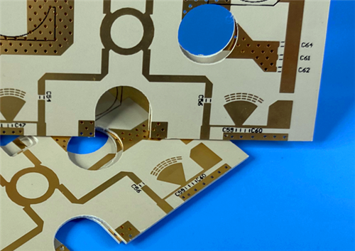
Rogers CLTE-MW 2-Layer High Frequency PCB – 2.9mil Low Loss Laminate for 5G and Millimeter Wave Application
Printed Circuit Boards are custom-made products; the images and specifications provided are for reference only.
1. CLTE-MW PCB Introduction
Rogers CLTE-MW is a high-performance copper clad laminate developed by Rogers Corporation. Engineered with ceramic-filled PTFE resin and spread woven fiberglass reinforcement, CLTE-MW laminate is designed exclusively for high frequency circuit applications with strict thickness limitations. This unique laminate system is available in 7 standard thickness options ranging from 3 mils to 10 mils, delivering optimal signal-to-ground spacing for modern 5G and millimeter wave circuit designs. The spread glass reinforcement structure, paired with high ceramic filler loading, effectively minimizes high frequency glass weave effects on electromagnetic wave propagation, ensuring stable and consistent signal transmission across high frequency bands.
Rogers 2-layer CLTE-MW PCB is built on the core advantages of Rogers’ proprietary CLTE-MW base material, creating a cost-effective, high-reliability high frequency circuit solution. It maintains excellent bonding compatibility with multiple types of copper foil, and its ultra-low loss characteristic, combined with smooth copper material, greatly optimizes insertion loss at high frequency bands, effectively reducing signal attenuation caused by skin effect loss. Fully compatible with conventional PTFE PCB processing workflows, Rogers CLTE-MW PCB supports standard shearing, drilling, milling and plating procedures, making it suitable for mass production of high frequency electronic devices.
2. CLTE-MW PCB Features
- Low Loss Tangent: 0.0015 at 10GHz
- Z-axis Coefficient of Thermal Expansion (CTE): 30 ppm/°C
- Thermal Conductivity: 0.42 W/(mK)
- UL94 V-0 Flammability Rating
- Low Moisture Absorption: 0.03%
- High Dielectric Strength: 630 V/mil
- Ultra-Thin Finished Board Thickness: 0.15mm
- 1oz (1.4 mils) Outer Layer Copper Weight
- Immersion Gold Surface Finish
- 100% Pre-Shipment Electrical Testing
3. CLTE-MW PCB Benefits
- Enables ultra-low loss high frequency circuit designs for 5G & millimeter wave applications
- Delivers excellent plated through hole (PTH) reliability for long-term operational stability
- Provides superior heat dissipation performance for high-density aggressive circuit designs
- Fully compatible with commercial, industrial and aerospace high frequency application requirements
- Maintains reliable mechanical performance under extreme thermal cycling environments
- Ultra-thin profile adapts to electronic devices with strict thickness limitations
- Offers outstanding dimensional stability for precision high-density PCB fabrication
- Delivers excellent cost-performance ratio for mass market high frequency electronic projects
4. PCB Construction Details
Item |
Specification |
Board Dimensions |
76.4mm x 95mm, 1PCS, +/- 0.15mm |
Minimum Trace/Space |
6/7 mils |
Minimum Hole Size |
0.25mm |
Blind Vias |
No Blind vias |
Finished Board Thickness |
0.15mm |
Finished Cu Weight |
1oz (1.4 mils) outer layers |
Via Plating Thickness |
20 μm |
Surface Finish |
Immersion Gold |
Top Silkscreen |
Black |
Bottom Silkscreen |
No |
Top Solder Mask |
No |
Bottom Solder Mask |
No |
Pre-Shipment Inspection |
100% Electrical test prior to shipment |
5. PCB Stackup
2-layer rigid PCBCopper_layer_1 - 35μm (1oz)CLTE-MW Core - 0.076 mm (2.99mil)Copper_layer_2 - 35μm (1oz)
6. PCB Statistics
- Components: 19
- Total Pads: 36
- Thru Hole Pads: 21
- Top SMT Pads: 15
- Bottom SMT Pads: 0
- Vias: 12
- Nets: 4
7. Type Of Artwork Supplied
Gerber RS-274-X
8. Quality Standard
IPC-Class-2
9. Availability
Worldwide
10. CLTE-MW PCB Applications
- 5G Millimeter Wave Communication Circuits & Systems
- Commercial Communications & Avionics Electronic Devices
- Military & Aerospace High Frequency RF Components
- Microwave Feed Networks & Antenna Arrays
- Phase Sensitive Electronic Structures & Precision Circuits
- Satellite Communication System On-Board Electronics
- RF Passive Components (Couplers, Filters, Baluns, Power Dividers)
- High Frequency Amplifiers, Oscillators & Transceiver Circuits
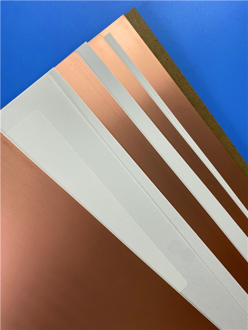
11. CLTE-MW CCL Base Material Knowledge
11.1 Material Overview
Rogers CLTE-MW is a professional-grade laminate specially developed by Rogers Corporation as a high-performance base material for modern high frequency and millimeter wave electronic applications. It adopts an advanced composite structure of ceramic filled polytetrafluoroethylene (PTFE) resin reinforced with spread woven fiberglass, delivering inherent low dielectric loss, stable thermal performance, and excellent mechanical rigidity. This unique laminate system is available in seven standard thickness options ranging from 3 mils to 10 mils, perfectly addressing the strict thickness limitations of modern 5G and millimeter wave circuit designs, while ensuring optimal signal-to-ground spacing for high frequency signal transmission.
The spread glass reinforcement design, combined with high ceramic filler loading, effectively minimizes the high frequency glass weave effects on electromagnetic wave propagation, ensuring stable and consistent signal transmission performance across high frequency bands. The woven fiberglass structure also provides outstanding long-term dimensional stability, making it ideal for high-density multilayer circuit manufacturing. As a cost-effective high frequency substrate from Rogers, CLTE-MW maintains standard industry lead times and fully adapts to the miniaturization trend of modern RF and microwave circuits. It offers superior bonding compatibility with a wide range of copper foil options, including rolled, reverse treated ED, and standard ED copper, with resistive foil and metal plate options available upon custom request.
Rogers CLTE-MW laminate is fully compatible with conventional PTFE PCB processing workflows, supporting standard shearing, drilling, milling, and plating procedures for mass production. Its low Z-axis thermal expansion coefficient ensures reliable plated through hole performance even under extreme thermal cycling, while its low moisture absorption of 0.03% guarantees stable electrical performance across varying operating environments. With a high dielectric strength of 630 V/mil, it delivers excellent z-axis insulation between conductor layers, making it suitable for high-voltage high frequency applications.
11.2 CLTE-MW CCL Core Benefits
- Ultra-low loss tangent of 0.0015 at 10GHz enables high-efficiency low loss high frequency circuit designs
- Low X, Y & Z-axis CTE delivers reliable mechanical performance under thermally challenging environments
- Excellent dimensional stability is critical for precise registration of small high-density circuit features
- 3-10mil available thickness options perfectly adapt to ultra-high frequency millimeter wave applications
- High thermal conductivity of 0.42 W/(mK) enables superior heat dissipation in aggressive high-density circuit designs
- UL94 V-0 flammability rating ensures full compliance with commercial and industrial safety requirements
- Low moisture absorption of 0.03% guarantees stable electrical performance in harsh operating environments
- Outstanding cost-performance ratio makes it ideal for mass market high frequency electronic projects
11.3 CLTE-MW CCL Typical Applications
- 5G Millimeter Wave Communication Circuits & Systems
- Commercial Communications & Avionics Electronic Devices
- Military & Aerospace High Frequency RF Components
- Microwave Feed Networks & Antenna Arrays
- Phase Sensitive Electronic Structures & Precision Circuits
- Satellite Communication System On-Board Electronics
- RF Passive Components (Couplers, Filters, Baluns, Power Dividers)
- High Frequency Amplifiers, Oscillators & Transceiver Circuits
12. DataSheet
Properties |
Typical Value1 |
Units |
Test Conditions |
Test Method |
Electrical Properties |
|
|
|
|
Dielectric Constant (process) |
2.94 to 3.02 ± 0.04 |
- |
23˚C @ 50% RH, 10 GHz |
IPC TM-650 2.5.5.5 |
Dielectric Constant (design) |
3.03 to 3.10 |
- |
C-24/23/50, 8-40 GHz |
Microstrip Differential Phase Length |
Dissipation Factor |
0.0015 |
- |
23˚C @ 50% RH, 10 GHz |
IPC TM-650 2.5.5.5 |
Thermal Coefficient of Dielectric Constant |
-35 |
ppm/˚C |
0 to 100˚C, 10 GHz |
IPC TM-650 2.5.5.5 |
Volume Resistivity |
1.3 x 10⁷ |
MΩ-cm |
C96/35/90 |
IPC TM-650 2.5.17.1 |
Surface Resistivity |
2.5 x 10⁶ |
MΩ |
C96/35/90 |
IPC TM-650 2.5.17.1 |
Electrical Strength (dielectric strength) |
630 |
V/mil |
- |
IPC TM-650 2.5.6.2 |
Dielectric Breakdown |
44 |
kV |
D-48/50 |
IPC TM-650 2.5.6 |
Comparative Tracking Index |
600V/ PLC 0 |
class/volts |
C-40/23/50 |
UL-746A, ASTM D6054 |
Thermal Properties |
|
|
|
|
Decomposition Temperature (Td) |
500 |
˚C |
2hrs @ 105˚C, 5% Weight Loss |
IPC TM-650 2.3.40 |
Coefficient of Thermal Expansion - x |
8 |
ppm/˚C |
-55˚C to 288˚C |
IPC TM-650 2.4.41 |
Coefficient of Thermal Expansion - y |
8 |
ppm/˚C |
- |
IPC TM-650 2.4.41 |
Coefficient of Thermal Expansion - z |
30 |
ppm/˚C |
- |
IPC TM-650 2.4.24 |
Thermal Conductivity |
0.42 |
W/(m.K) |
Z Direction |
ASTM D5470 |
Time to Delamination |
>60 |
minutes |
288˚C |
IPC TM-650 2.4.24.1 |
Mechanical Properties |
|
|
|
|
Copper Peel Strength |
1.1 (6.0) |
N/mm (lbs/in) |
as-received, 10s @288˚C, 35 μm foil |
IPC TM-650 2.4.8 |
Flexural Strength (MD, CMD) |
113, 99 (16.4, 14.4) |
MPa (ksi) |
25˚C +/- 3˚C |
ASTM D790 |
Tensile Strength (MD, CMD) |
83, 80 (12.0, 11.6) |
MPa (ksi) |
23˚C @ 50% RH |
ASTM D3039/D3039-14 |
Flex Modulus (MD, CMD) |
6468, 6360 (938.1, 922.4) |
MPa (ksi) |
25˚C +/- 3˚C |
IPC TM-650 2.4.4 |
Dimensional Stability (MD, CMD) |
0.22, 0.22 |
mil/inch |
after etch + bake |
IPC-TM-650 2.4.39a |
Physical Properties |
|
|
|
|
Flammability |
V-0 |
- |
- |
UL 94 |
Moisture Absorption |
0.03 |
% |
E1/105+D48/50 |
IPC TM-650 2.6.2.1 |
Density |
2.1 |
g/cm³ |
C24/23/50 |
ASTM D792 |
Specific Heat Capacity |
0.93 |
J/g˚K |
2 hours at 105˚C |
ASTM E2716 |
NASA Outgassing - Total Mass Lost (TML) |
0.03 |
% |
- |
ASTM E595 |
NASA Outgassing - Collected Volatiles (CVCM) |
<0.01 |
% |
- |
ASTM E595 |
13. Summary
Rogers CLTE-MW 2-Layer 0.15mm High Frequency PCB is a cost-effective, ultra-thin rigid circuit board built with advanced ceramic filled PTFE and spread woven fiberglass substrate from Rogers Corporation. With stable ultra-low loss high frequency performance, excellent thermal management capability, precise dimensional stability, and reliable mechanical performance under extreme environments, Rogers CLTE-MW 2-Layer PCB fully adapts to 5G millimeter wave communication, aerospace, satellite, and industrial high frequency electronic projects. It supports global supply chain coverage and fully meets IPC Class 2 quality standard requirements for mass production.
Tags:Rogers CLTE-MW PCB, 2 Layer CLTE-MW High Frequency PCB, 0.15mm Thin Rigid PCB, Immersion Gold Surface Finish PCB, IPC Class 2 High Frequency PCB, Ceramic Filled PTFE CCL, Rogers CLTE-MW Copper Clad Laminate, 5G Millimeter Wave PCB, Aerospace High Frequency PCB, Low Loss RF Base Material, Microwave Circuit PCB, Satellite Communication PCB, Rogers High Frequency Material