

 Home
-
Newly shipped PCBs
-
Taconic RF-10 2-Layer 10mil High Frequency PCB – high dielectric constant laminate for RF circuit designs
Home
-
Newly shipped PCBs
-
Taconic RF-10 2-Layer 10mil High Frequency PCB – high dielectric constant laminate for RF circuit designs
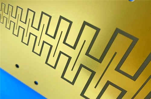
Taconic RF-10 2-Layer 10mil High Frequency PCB – high dielectric constant laminate for RF circuit designs
Printed Circuit Boards are custom-made products; the images and specifications provided are for reference only.
1. Introduction
Taconic RF-10 is a high-performance copper clad laminate composed of ceramic filled PTFE resin combined with woven fiberglass reinforcement. Taconic RF-10 PCB material delivers a high dielectric constant alongside an ultra-low dissipation factor for reliable high frequency circuit performance. Adopting thin woven fiberglass structure, RF-10 PCB achieves low dielectric loss, enhanced structural rigidity for easy fabrication handling, and superior dimensional stability suitable for multilayer circuit design requirements.
Engineered as a cost-effective high frequency substrate with standard industry lead time availability, RF-10 printed circuit board perfectly meets the market demand for miniaturized RF circuit designs. It maintains excellent bonding compatibility with smooth low-profile copper foil. The low dissipation factor property of RF-10 laminate, matched with ultra-smooth copper material, minimizes skin effect loss at high frequency bands and realizes optimized insertion loss performance for high frequency application scenarios.
2. RF-10 PCB Features
- Dielectric Constant: 10.2 ± 0.3 at 10GHz
- Dissipation Factor: 0.0025 at 10GHz
- Unclad Thermal Conductivity: 0.85 W/mk
- X Axis CTE: 16 ppm/°C, Y Axis CTE: 20 ppm/°C, Z Axis CTE: 25 ppm/°C
- Low Moisture Absorption: 0.08%
- Flammability Rating: V-0 Fire Resistance Grade
3. RF-10 PCB Benefits
- High DK Value Supports RF Circuit Size Reduction
- Outstanding Dimensional Stability for Precision PCB Fabrication
- Strict Dielectric Constant Tolerance at 10.2 ± 0.3
- High Thermal Conductivity Improves Overall Thermal Management Performance
- Superior Adhesion Compatibility With Smooth Low-Profile Copper Foil
- Low X, Y, Z Axis Thermal Expansion Reduces Deformation Risk
- Excellent Cost-Performance Ratio for Commercial High Frequency Projects
4. PCB Construction Details
Item |
Specification |
Board Dimensions |
143.6mm x 109.8mm, 2 Types, 2PCS, +/- 0.15mm |
Minimum Trace/Space |
5/7 mils |
Minimum Hole Size |
0.4mm |
Blind Vias |
No Blind vias |
Finished Board Thickness |
0.5mm |
Finished Cu Weight |
1oz (1.4 mils) outer layers |
Via Plating Thickness |
20 μm |
Surface Finish |
ENEPIG |
Top Silkscreen |
No |
Bottom Silkscreen |
No |
Top Solder Mask |
No |
Bottom Solder Mask |
No |
Pre-Shipment Inspection |
100% Electrical test prior to shipment |
5. PCB Stackup
2-layer rigid PCBCopper_layer_1 - 35μm (1oz)RF-10 Core - 10mil (0.254mm)Copper_layer_2 - 35μm (1oz)
6. PCB Statistics
Components: 24
Total Pads: 51
Thru Hole Pads: 34
Top SMT Pads: 17
Bottom SMT Pads: 0
Vias: 29
Nets: 2
7. Type Of Artwork Supplied
Gerber RS-274-X
8. Quality Standard
IPC-Class-2
9. Availability
Worldwide
10. RF-10 PCB Applications
- Microstrip Patch Antennas
- GPS Antennas
- Passive Components (Filters, Couplers, Power Dividers)
- Aircraft Collision Avoidance Systems
- Satellite Components
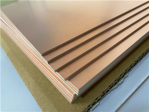
11. RF-10 CCL Base Material Knowledge
11.1 Material Overview
Taconic RF-10 is a professional copper clad laminate specially developed as the base material for high power RF electronic applications. It adopts a composite structure of ceramic filled PTFE and woven fiberglass, featuring inherent high dielectric constant and low dissipation factor. The thin woven fiberglass reinforcement design enables low dielectric loss, better structural rigidity for easy processing, and stable dimensional performance ideal for multilayer circuit manufacturing.
As a cost-efficient high frequency substrate, RF-10 high-frequency laminate maintains standard industrial delivery cycles and perfectly satisfies the miniaturization trend of modern RF circuits. It shows superior bonding performance with smooth low-profile copper foil. Its ultra-low loss characteristic cooperates with smooth copper to greatly optimize insertion loss at high frequency bands, effectively reducing signal attenuation caused by skin effect loss. Taconic RF-10 high-frequency material is fully compatible with conventional PTFE PCB processing flow, supporting standard shearing, drilling, milling and plating procedures. With low X, Y, Z thermal expansion coefficients, it ensures reliable plated through hole performance and lowers artwork compensation deviation for mass production.
11.2 RF-10 CCL Core Benefits
- High DK value enables miniaturization design of RF circuits
- Superior long-term dimensional stability
- Precise DK tolerance controlled at 10.2 ± 0.3
- Ultra-low loss tangent of 0.0025 at 10 GHz
- High thermal conductivity to strengthen heat dissipation and thermal management
- Perfect adhesion capability with smooth copper foil
- Low X, Y, Z thermal expansion coefficient
- Premium cost-performance ratio for high frequency projects
11.3 RF-10 CCL Typical Applications
- Microstrip Patch Antennas
- GPS Antennas
- RF Passive Components including Filters, Couplers and Power Dividers
- Aircraft Collision Avoidance Systems
- Satellite Electronic Components
12.DataSheet
Property Category |
Property Item |
Test Condition |
Typical Value |
Unit |
Test Method |
Electrical Properties |
Dielectric Constant |
@ 10 GHz |
10.2 ± 0.3 |
- |
IPC-650 2.5.5.5.1 Mod. |
|
Dissipation Factor |
@ 10 GHz |
0.0025 |
- |
IPC-650 2.5.5.5.1 Mod. |
|
Surface Resistivity |
- |
1.0 x 10⁸ |
Mohms |
IPC-650 2.5.17.1 |
|
Volume Resistivity |
- |
6.0 x 10⁷ |
Mohms/cm |
IPC-650 2.5.17.1 |
Thermal Properties |
Thermal Conductivity |
Unclad |
0.85 |
W/M*K |
IPC-650-2.4.50 |
|
Coefficient of Thermal Expansion (CTE, RT-150 °C) |
X-Axis |
16 |
ppm/°C |
IPC-650 2.4.41 |
|
|
Y-Axis |
20 |
ppm/°C |
- |
|
|
Z-Axis |
25 |
ppm/°C |
- |
|
Temperature Coefficient of Thermal Expansion (TcK†, -55 to 150 °C) |
- |
-370 |
ppm/°C |
IPC-650 2.5.5.6 |
Mechanical Properties |
Flexural Strength |
MD (Machine Direction) |
96.53 (14,000) |
N/mm² (psi) |
IPC-650-2.4.4 |
|
|
CD (Cross Direction) |
68.95 (10,000) |
N/mm² (psi) |
- |
|
Tensile Strength |
MD (Machine Direction) |
62.57 (8,900) |
N/mm² (psi) |
IPC-650-2.4.19 |
|
|
CD (Cross Direction) |
37.26 (5,300) |
N/mm² (psi) |
- |
Dimensional Stability |
Dimensional Change Rate |
25mil-MD, After Etch |
-0.0032 |
% |
IPC-650 2.4.39 |
|
|
25mil-CD, After Etch |
-0.0239 |
% |
- |
|
|
25mil-MD, After Bake |
-0.0215 |
% |
IPC-650 2.4.39 |
|
|
25mil-CD, After Bake |
-0.0529 |
% |
- |
|
|
25mil-MD, After Stress |
-0.0301 |
% |
IPC-650 2.4.39 |
|
|
25mil-CD, After Stress |
-0.0653 |
% |
- |
|
|
60mil-MD, After Etch |
-0.0027 |
% |
IPC-650 2.4.39 |
|
|
60mil-CD, After Etch |
-0.0142 |
% |
- |
|
|
60mil-MD, After Bake |
-0.1500 |
% |
IPC-650 2.4.39 |
|
|
60mil-CD, After Bake |
-0.0326 |
% |
- |
|
|
60mil-MD, After Stress |
-0.0167 |
% |
IPC-650 2.4.39 |
|
|
60mil-CD, After Stress |
-0.0377 |
% |
- |
Chemical & Physical Properties |
Moisture Absorption |
- |
0.08 |
% |
IPC-650 2.6.2.1 |
|
Peel Strength |
1 oz. RT Copper Foil |
1.7 |
N/mm |
IPC-650 2.4.8 (solder) |
|
Density |
Specific Gravity |
2.77 |
g/cm³ |
IPC-650-2.3.5 |
|
Specific Heat Capacity |
- |
0.90 |
J/g°C |
IPC-650-2.4.50 |
|
Flammability Rating |
- |
V-0 |
- |
Internal Test |
13.Summary
Taconic RF-10 2-Layer High Frequency PCB is a cost-effective rigid circuit board built with ceramic filled PTFE and woven fiberglass substrate. With stable dielectric performance, low loss, good thermal conductivity and precise dimensional stability, RF-10 2-Layer PCB fully adapts to high frequency RF, communication, aerospace and satellite electronic projects, supporting global supply and IPC Class 2 quality standard requirements.
Tags:RF-10 PCB, 2 Layer RF-10 High Frequency PCB, 0.5mm Thick Rigid PCB, ENEPIG Surface Finish PCB, IPC Class 2 High Frequency PCB, Ceramic Filled PTFE CCL, RF-10 Copper Clad Laminate, GPS Antenna PCB, Microstrip Patch Antenna PCB, Aerospace High Frequency PCB, High Power RF Base Material