


 Home
-
Newly shipped PCBs
-
F4BTMS265 30mil 2-Layer ENIG PCB High Reliability Rigid Circuit Material for Aerospace, Radar and Microwave Applications
Home
-
Newly shipped PCBs
-
F4BTMS265 30mil 2-Layer ENIG PCB High Reliability Rigid Circuit Material for Aerospace, Radar and Microwave Applications
F4BTMS265 30mil 2-Layer ENIG PCB High Reliability Rigid Circuit Material for Aerospace, Radar and Microwave Applications
Printed Circuit Boards are custom-made products; the images and specifications provided are for reference only.
1. Introduction of F4BTMS265 PCB
F4BTMS265 PCB is a high-performance 2-layer rigid high-frequency circuit board adopting the upgraded F4BTMS series substrate. As an advanced iteration of the classic F4BTM material, F4BTMS achieves major breakthroughs in formula design and manufacturing processes. Reinforced by ultra-thin and ultra-fine fiberglass cloth and filled with massive ceramic fillers, this aerospace-grade material delivers comprehensive performance upgrades and a wider range of dielectric constant options, serving as a competent alternative to imported equivalent high-frequency materials.
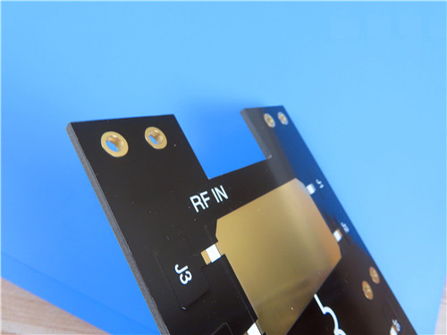
30mil F4BTMS265 laminate PCB features an ENIG surface finish and a finished thickness of 0.85mm. Its composite structure combining PTFE resin, uniformly dispersed nano-ceramics and lightweight fine fiberglass minimizes the fiberglass effect during electromagnetic transmission, bringing ultra-low dielectric loss and superior overall stability. Equipped with standard RTF low-roughness copper foil, it cuts conductor loss while maintaining remarkable peel strength, and supports matching with copper base or aluminum base. Every board is 100% electrically inspected before delivery, and F4BTMS265 is available for global supply for aerospace, military radar and satellite communication projects.
2. Key Features of F4BTMS265 PCB
- Built with F4BTMS265 PTFE composite substrate filled with ceramics and reinforced by ultra-thin ultra-fine fiberglass cloth
- Fixed dielectric constant (Dk): 2.65 at 10GHz with tight tolerance and excellent batch consistency
- Low dissipation factor: 0.0012 at 10GHz, 0.0014 at 20GHz, realizing ultra-low signal attenuation
- Thermal expansion coefficient: 15 ppm/°C (X-axis), 20 ppm/°C (Y-axis), 72 ppm/°C (Z-axis) within -55°C ~ 288°C
- Low thermal coefficient of Dk: -88 ppm/°C in the range of -55°C to 150°C
- UL 94-V0 flame retardant rating for high safety performance
- Ultra-low moisture absorption rate of 0.025%, resisting performance drift in humid environments
- No blind via design, simplifying layout and improving production yield
- 1oz outer copper weight and 20 μm via plating thickness ensure stable conductivity and structural reliability
- Custom silkscreen and solder mask: white top silkscreen, black top solder mask, no coating on the bottom side
3. Product Benefits
- Suppressed Fiberglass Effect: The optimized material formula greatly weakens adverse impacts on electromagnetic wave propagation, ideal for phase-sensitive high-frequency applications.
- Low Anisotropy: Reduced X/Y/Z axis anisotropy improves dimensional stability of PCBs during processing and operation.
- Wide Frequency Compatibility: Maintains stable Dk and low loss up to 40GHz, covering mainstream microwave and RF frequency bands.
- Outstanding Temperature Stability: Steady electrical properties across -55°C to 150°C adapt to extreme temperature working conditions.
- High Power Bearing Capacity: Enhanced thermal conductivity effectively dissipates heat, suitable for high-power circuit designs.
- Strong Environmental Adaptability: Excellent radiation resistance and low outgassing performance fully meet aerospace vacuum environment requirements.
- Flexible Structural Matching: Compatible with copper base, aluminum base and diversified copper foil solutions for multiple design demands.
- Good Processability: Matches standard PTFE PCB fabrication techniques, supporting dense holes and fine line processing.
4. PCB Construction Details
Parameter Item |
Specification Details |
Base Material |
F4BTMS265 PTFE Ceramic Filled Substrate |
Layer Count |
2-Layer Rigid PCB |
Board Dimensions |
97mm x 76mm (1PCS), Tolerance: +/- 0.15mm |
Minimum Trace/Space |
14/14 mils |
Minimum Hole Size |
0.25mm |
Blind Vias |
No Blind Vias |
Finished Board Thickness |
0.85mm |
Finished Cu Weight |
1oz (1.4 mils) Outer Layers |
Via Plating Thickness |
20 μm |
Surface Finish |
ENIG |
Top Silkscreen |
White |
Bottom Silkscreen |
No |
Top Solder Mask |
Black |
Bottom Solder Mask |
No |
Pre-Shipment Test |
100% Electrical Test Prior to Shipment |
5. PCB Stackup
This 2-layer rigid F4BTMS265 PCB adopts a symmetrical stackup structure with 30mil high-performance composite core, delivering balanced electrical, thermal and mechanical performance for high-frequency aerospace and military circuits.
- Copper Layer 1: 35 μm Finished Copper
- F4BTMS265 Core: 30mil (0.762 mm)
- Copper Layer 2: 35 μm Finished Copper
6. PCB Statistics
- Total Components: 39
- Total Pads: 67
- Thru Hole Pads: 41
- Top SMT Pads: 26
- Bottom SMT Pads: 0
- Total Vias: 25
- Total Nets: 2
7. Artwork & Production Standard
- Supplied Artwork Type: Gerber RS-274-X
- Manufacturing Quality Standard: IPC-Class-2
- Product Availability: Worldwide
8. Typical PCB Applications
- Aerospace equipment, spacecraft and cabin electronic devices
- Microwave and RF circuit systems
- Civil radar and military radar equipment
- Antenna feed network modules
- Phase-sensitive antennas and phased array antenna systems
- Satellite communication systems
9. F4BTMS & F4BTMS265 Copper Clad Laminate Introduction
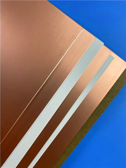
F4BTMS series is a high-grade PTFE copper clad laminate reinforced with ultra-thin & ultra-fine fiberglass cloth and filled with ceramic particles, an upgraded version of the traditional F4BTM series. With innovative material formulas and optimized production technologies, this aerospace-reliable CCL is blended with abundant nano-ceramic fillers and reinforced by fine fiberglass, achieving comprehensive performance improvement and a richer selection of dielectric constants. It is a perfect replacement for imported high-frequency laminates for high-reliability scenarios.
F4BTMS substrate takes PTFE resin as the base material, mixed with large quantities of uniformly distributed special nano-ceramics and a small amount of ultra-thin ultra-fine fiberglass cloth. This unique composition minimizes the fiberglass effect during electromagnetic transmission and lowers dielectric loss significantly. Meanwhile, the material features reduced three-dimensional anisotropy, elevated electrical strength and thermal conductivity, as well as low thermal expansion coefficient and stable dielectric temperature characteristics.
All F4BTMS series laminates are equipped with RTF low-roughness copper foil as standard configuration. This design effectively reduces conductor loss while retaining excellent peel strength. The laminates can be combined with copper base or aluminum base according to project requirements. In addition, the F4BTMS294 variant can be paired with embedded 50Ω resistance copper foil to produce integrated resistance film laminates.
In terms of manufacturability, F4BTMS series laminate is fully compatible with standard PTFE PCB processing technologies. Thanks to superior mechanical and physical properties, it is well suited for multi-layer, high-layer-count PCBs and backboard fabrication, and presents excellent process performance for dense via holes and fine circuit traces.
9.1 Core Features of F4BTMS Series CCL
- Small tolerance of dielectric constant and outstanding consistency across production batches
- Ultra-low dielectric loss for high-efficiency high-frequency signal transmission
- Maintains stable Dk and low loss up to 40GHz, perfectly fitting phase-sensitive applications
- Excellent temperature coefficient of dielectric properties, ensuring stable frequency and phase performance from -55°C to 150°C
- Superior radiation resistance; dielectric and physical properties remain stable after high-dose radiation exposure
- Low outgassing performance, fully compliant with vacuum outgassing standards for aerospace applications
- Low thermal expansion coefficient in X/Y/Z directions, guaranteeing dimensional thermal stability and reliable plated through holes
- Enhanced thermal conductivity to meet the demands of high-power electronic equipment
- Excellent overall dimensional stability for long-term service
- Ultra-low water absorption to avoid performance degradation in humid working environments
9.2 Processing & Structural Advantages of F4BTMS CCL
- Fully compatible with standard PTFE PCB production workflows, no special equipment or complex procedures required
- Outstanding machinability for dense vias and fine traces, supporting high-precision PCB manufacturing
- Ideal for manufacturing multi-layer, high-layer-count boards and backplanes thanks to robust mechanical properties
- Diverse structural customization: available for copper base, aluminum base lamination, and embedded 50Ω resistance copper foil design
- Aerospace-grade material properties deliver stable performance under radiation and vacuum working conditions
9.3 Main Application Scenarios of F4BTMS Series CCL
- Aerospace equipment, space vehicles and onboard cabin electronics
- Microwave and RF signal circuit systems
- Military radar and conventional radar devices
- Antenna feed network assemblies
- Phase-sensitive antennas and phased array antenna systems
- Satellite communication hardware and related modules
10.Datasheet
Item |
Test Condition |
Unit |
F4BTMS265 |
Typical Dielectric Constant |
10GHz |
/ |
2.65 |
Dielectric Constant Tolerance |
/ |
/ |
±0.04 |
Design Dielectric Constant |
10GHz |
/ |
2.65 |
Typical Dissipation Factor |
10GHz |
/ |
0.0012 |
Typical Dissipation Factor |
20GHz |
/ |
0.0014 |
Typical Dissipation Factor |
40GHz |
/ |
0.0018 |
Temperature Coefficient of Dielectric Constant |
-55℃ ~ 150℃ |
PPM/℃ |
-88 |
Peel Strength |
1 OZ RTF Copper Foil |
N/mm |
>1.8 |
Volume Resistivity |
Normal Temperature |
MΩ·cm |
≥1×10⁸ |
Surface Resistivity |
Normal Temperature |
MΩ |
≥1×10⁸ |
Dielectric Strength (Z-axis) |
5KW, 500V/s |
KV/mm |
>34 |
Breakdown Voltage (XY-axis) |
5KW, 500V/s |
KV |
>42 |
Coefficient of Thermal Expansion (X, Y-axis) |
-55℃ ~ 288℃ |
ppm/℃ |
15~20 |
Coefficient of Thermal Expansion (Z-axis) |
-55℃ ~ 288℃ |
ppm/℃ |
72 |
Thermal Stress |
260℃, 10s, 3 cycles |
/ |
No Delamination |
Water Absorption |
20±2℃, 24h |
% |
0.025 |
Density |
Normal Temperature |
g/cm³ |
2.26 |
Continuous Operating Temperature |
Temperature Chamber |
℃ |
-55 ~ +260 |
Thermal Conductivity (Z-axis) |
/ |
W/(M·K) |
0.36 |
Flame Retardancy |
/ |
UL-94 |
V-0 |
Material Composition |
/ |
/ |
PTFE, Ultra-thin & Ultra-fine Glass Fiber, Ceramic |
11. Product Overall Summary
F4BTMS265 2-Layer 30mil ENIG PCB is an aerospace-grade high-frequency rigid board built on upgraded F4BTMS composite laminate. With stable electrical parameters, ultra-low loss, great temperature and radiation resistance, it supports standard PTFE processing and diverse structural collocation. Complying with IPC-Class-2 standards, this cost-effective alternative to foreign materials is widely used in aerospace, military radar, antennas and satellite communication fields worldwide.
Tags:F4BTMS265 PCB, 30mil High Frequency PCB, F4BTMS265 ENIG PCB, F4BTMS265 Aerospace PCB, PTFE Ceramic Filled Laminate, RF Microwave PCB, Dk 2.65 High Reliability PCB, Military Radar PCB, Satellite Communication PCB, Phased Array Antenna PCB, IPC-Class-2 PCB, Radiation Resistant PCB, Low Outgassing PCB