
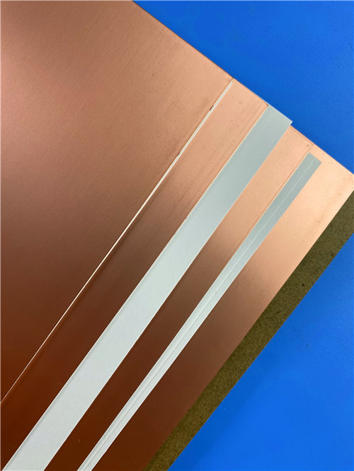
F4BTMS265 High Frequency Laminates Introduction F4BTMS265 high frequency material marks a standout upgrade in the F4BTM series, integrating advanced ceramic loading and ultra-fine glass reinforcement to deliver exceptional electrical and mechanical performance. This enhanced formulation equips designers with a wider range of dielectric properties while upholding outstanding dimensional stability and thermal characteristics – making F4BTMS265 an ideal choice for high-demand RF applications. Engineered with specialized nano-ceramics uniformly dispersed in a PTFE resin matrix, F4BTMS265 PCB raw material minimizes fiberglass interference during electromagnetic wave propagation. This unique composition translates to reduced dielectric loss, improved thermal conductivity, and enhanced multi-axial dimensional stability for F4BTMS265, ensuring consistent performance across extended frequency ranges and excellent dielectric temperature stability. F4BTMS265 laminate comes standard with RTF low-profile copper foil, enabling optimal signal integrity by reducing conductor loss while maintaining strong peel strength. The versatile F4BTMS265 PCB substrate supports both traditional and metal-core configurations, offering designers flexible thermal management solutions to meet diverse project requirements. Compatible with standard PTFE processing techniques, F4BTMS265 PCB substrate facilitates reliable fabrication of complex multilayer boards, high-density interconnects, and sophisticated backplane designs. Its balanced mechanical properties empower fine-line patterning and dense via structures – critical features for advanced RF systems that rely on F4BTMS265’s consistent performance. As a high-reliability material meeting stringent aerospace standards, F4BTMS265 laminate serves as a dependable domestic alternative to international high-frequency laminates, without compromising on performance, manufacturability, or durability. For projects demanding precision and consistency, F4BTMS265 stands out as a trusted solution in the high-frequency material landscape. Product Features - Minimal dielectric constant tolerance and excellent batch-to-batch consistency. - Extremely low dielectric loss. - Stable dielectric constant and low loss within frequencies up to 40GHz, meeting the requirements of phase-sensitive applications. - Excellent temperature coefficient of dielectric constant and dielectric loss, maintaining frequency and phase stability between -55°C and 150°C. - Excellent resistance to radiation, retaining stable dielectric and physical properties even after exposure to irradiation. - Low outgassing performance, meeting the vacuum outgassing requirements for aerospace applications. - Minimal thermal expansion coefficients in the X/Y/Z directions, ensuring dimensional stability and reliable hole copper connections. - Improved thermal conductivity, suitable for high-power applications. - Excellent dimensional stability. - Low water absorption. Models & Data Sheet Here are the technical parameters of the different product models: Product Models: F4BTMS220 F4BTMS233 F4BTMS255 F4BTMS265 F4BTMS294 F4BTMS300 F4BTMS350 F4BTMS430 F4BTMS450 F4BTMS615 F4BTMS1000 Dielectric Constant (Typical): Test Conditions: 10 GHz Values: F4BTMS220: 2.2 F4BTMS233: 2.33 F4BTMS255: 2.55 F4BTMS265: 2.65 F4BTMS294: 2.94 F4BTMS300: 3.00 F4BTMS350: 3.50 F4BTMS430: 4.30 F4BTMS450: 4.50 F4BTMS615: 6.15 F4BTMS1000: 10.20 Dielectric Constant Tolerance: Values: F4BTMS220: +/-0.02; F4BTMS233: +/-0.03; F4BTMS255: +/-0.04; F4BTMS265: +/-0.04; F4BTMS294: +/-0.04; F4BTMS300: +/-0.04; F4BTMS350: +/-0.04; F4BTMS430: +/-0.05; F4BTMS450: +/-0.09; F4BTMS615: +/-0.09; F4BTMS1000: +/-0.12 Dielectric Constant (Design): Test Conditions: 10 GHz Values are the same as the "Dielectric Constant (Typical)" section. Loss Tangent (Typical): Test Conditions: 10 GHz 20 GHz 40 GHz Values: F4BTMS220: 10 GHz: 0.0009 20 GHz: 0.0010 40 GHz: 0.0013 F4BTMS233: 10 GHz: 0.0010 20 GHz: 0.0011 40 GHz: 0.0015 F4BTMS255: 10 GHz: 0.0012 20 GHz: 0.0013 40 GHz: 0.0016 F4BTMS265: 10 GHz: 0.0012 20 GHz: 0.0014 40 GHz: 0.0018 F4BTMS294: 10 GHz: 0.0012 20 GHz: 0.0014 40 GHz: 0.0018 F4BTMS300: 10 GHz: 0.0013 20 GHz: 0.0015 40 GHz: 0.0019 F4BTMS350: 10 GHz: 0.0016 20 GHz: 0.0019 40 GHz: 0.0024 F4BTMS350: 10 GHz: 0.0016 20 GHz: 0.0019 40 GHz: 0.0024 F4BTMS450: 10 GHz: 0.0015 20 GHz: 0.0019 40 GHz: 0.0024 F4BTMS615: 10 GHz: 0.0020 20 GHz: 0.0023 40 GHz: / F4BTMS1000: 10 GHz: 0.0020 20 GHz: 0.0023 40 GHz: / Product Technical Parameters Product Models & Data Sheet Product Features Test Conditions Unit F4BTMS220 F4BTMS233 F4BTMS255 F4BTMS265 F4BTMS294 F4BTMS300 F4BTMS350 F4BTMS430 F4BTMS450 F4BTMS615 F4BTMS1000 Dielectric Constant (Typical) 10GHz / 2.2 2.33 2.55 2.65 2.94 3.00 3.50 4.30 4.50 6.15 10.20 Dielectric Constant Tolerance / / ±0.02 ±0.03 ±0.04 ±0.04 ±0.04 ±0.04 ±0.05 ±0.09 ±0.09 ±0.12 ±0.2 Dielectric Constant (Design) 10GHz / 2.2 2.33 2.55 2.65 2.94 3.0 3.50 4.3 4.5 6.15 10.2 Loss Tangent (Typical) 10GHz / 0.0009 0.0010 0.0012 0.0012 0.0012 0.0013 0.0016 0.0015 0.0015 0.0020 0.0020 20GHz / 0.0010 0.0011 0.0013 0.0014 0.0014 0.0015 0.0019 0.0019 0.0019 0.0023 0.0023 40GHz / 0.0013 0.0015 0.0016 0.0018 0.0018 0.0019 0.0024 0.0024 0.0024 / / Dielectric Constant Temperature Coefficient -55 º~150ºC PPM/℃ -130 -122 -92 -88 -20 -20 -39 -60 -58 -96 -320 Peel Strength 1 OZ RTF copper N/mm >2.4 >2.4 >1.8 >1.8 >1.2 >1.2 >1.2 >1.2 >1.2 >1.2 >1.2 Volume Resistivity Standard Condition MΩ.cm ≥1×10^8 ≥1×10^8 ≥1×10^8 ≥1×10^8 ≥1×10^8 ≥1×10^8 ≥1×10^8 ≥1×10^8 ≥1×10^8 ≥1×10^8 ≥1×10^8 Surface Resistivity Standard Condition MΩ ≥1×10^8 ≥1×10^8 ≥1×10^8 ≥1×10^8 ≥1×10^8 ≥1×10^8 ≥1×10^8 ≥1×10^8 ≥1×10^8 ≥1×10^8 ≥1×10^8 Electrical Strength (Z direction) 5KW, 500V/s KV/mm >26 >30 >32 >34 >40 >40 >42 >44 >45 >48 >23 Breakdown Voltage (XY direction) 5KW, 500V/s KV >35 >38 >40 >42 >48 >52 >55 >52 >54 >55 >42 Coefficientof Thermal Expansion (X, Y direction) -55 º~288ºC ppm/ºC 40, 50 35, 40 15, 20 15, 20 10, 12 10, 11 10, 12 13, 12 12, 12 10, 12 16, 18 Coefficientof Thermal Expansion (Z direction) -55 º~288ºC ppm/ºC 290 220 80 72 22 22 20 47 45 40 32 Thermal Stress 260℃, 10s, 3 times / No delamination No delamination No delamination No delamination No delamination No delamination No delamination No delamination No delamination No delamination No delamination Water Absorption 20±2℃, 24 hours % 0.02 0.02 0.025 0.025 0.02 0.025 0.03 0.08 0.08 0.1 0.03 Density Room Temperature g/cm3 2.18 2.22 2.26 2.26 2.25 2.28 2.3 2.51 2.53 2.75 3.2 Long-Term Operating Temperature High-Low Temperature Chamber ℃ -55~+260 -55~+260 -55~+260 -55~+260 -55~+260 -55~+260 -55~+260 -55~+260 -55~+260 -55~+260 -55~+260 Thermal Conductivity Z direction W/(M.K) 0.26 0.28 0.31 0.36 0.58 0.58 0.6 0.63 0.64 0.67 0.81 Flammability / UL-94 V-0 V-0 V-0 V-0 V-0 V-0 V-0 V-0 V-0 V-0 V-0 Material Composition / / PTFE, Ultra-thin and ultra-fine (quartz) fiberglass. PTFE, Ultra-thin and ultra-fine fiberglass, ceramics. A F4BTMS Laminate and Typical Applications: Presented on the screen is an F4BTMS high-frequency substrate . F4BTMS laminates are extensively employed in various domains, including: Aerospace and aviation equipment, space installations, and cabin setups. Microwave and RF applications. Radar systems, particularly in military applications. Feed networks for signal distribution. Phase-sensitive antennas and phased array antennas. Satellite communications, and much more. Final (F4BTMS series aluminum-based/copper-based boards) This series of laminates can provide aluminum-based or copper-based materials, where one side of the dielectric layer is covered with copper foil, and the other side is covered with an aluminum-based or copper-based layer. This configuration serves as shielding or heat dissipation. Engineered to meet the rigorous demands of advanced aerospace, defense, and telecommunications applications, F4BTMS265 high-frequency laminate delivers exceptional electrical stability, minimal dielectric variation, and ultra-low loss performance up to 40 GHz. This ensures F4BTMS265 maintains consistent signal integrity and phase accuracy in even the most demanding high-frequency systems, a critical advantage for mission-critical designs. F4BTMS265 PCB material also boasts outstanding thermal and environmental resilience, including radiation resistance, low outgassing, and stable performance across extreme temperature ranges. Complemented by enhanced thermal conductivity, superior dimensional stability, and strong moisture resistance, F4BTMS265 high-frequency circuit material provides a robust, high-performance foundation for next-generation RF, microwave, and multilayer PCB applications that rely on unwavering reliability.


 Home
Home