


 Home
-
Newly shipped PCBs
-
F4BTD350S Double Sided RF Circuit Board 20mil F4BTD350S Laminate PCB for High Power RF Amplifiers
Home
-
Newly shipped PCBs
-
F4BTD350S Double Sided RF Circuit Board 20mil F4BTD350S Laminate PCB for High Power RF Amplifiers
F4BTD350S Double Sided RF Circuit Board 20mil F4BTD350S Laminate PCB for High Power RF Amplifiers
Printed Circuit Boards are custom-made products; the images and specifications provided are for reference only.
1. Introduction
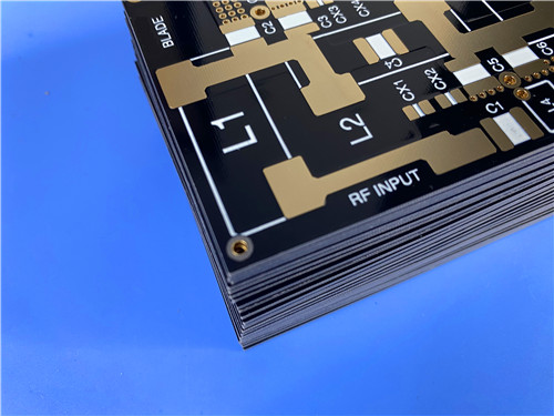
Engineered around high thermal conductivity ceramic loaded PTFE dielectric, F4BTD350S double sided RF PCB is a rigid high-frequency circuit solution tailored for high-power microwave equipment. With a finished overall thickness of 0.6mm and premium Immersion Gold surface metallization, this custom circuit board complies with IPC-Class-2 industrial quality norms and supports global manufacturing and shipment. Its core dielectric F4BTD350S adopts glass fabric reinforcement mixed with high-heat-transfer ceramic fillers, delivering two core strengths: ultra-low signal loss and superior heat dissipation capacity. As a cost-effective domestic substitute for imported high-power RF laminates, it perfectly fits production of power amplifiers, microwave antennas, industrial heating modules and passive microwave components including couplers and filters. Stable electrical parameters across wide temperature ranges and tight dimensional tolerances allow seamless fabrication of fine traces and dense hole layouts for devices running long hours under continuous high-temperature conditions.
2. Core Electrical & Thermal Characteristics of F4BTD350S Substrate
- Fixed Dielectric Constant (Dk): 3.5±0.07 tested at 10GHz
- Low Dissipation Factor (Df): 0.0016 at 10GHz
- High Thermal Conductivity Index: 1.25 W/MK
- Triple-axis CTE data: X-axis 11 ppm/°C, Y-axis 10 ppm/°C, Z-axis 40 ppm/°C (-55°C ~ 288°C)
- Low TCDK rating: -45 ppm/°C within -55°C to 150°C working temperature range
- Comparative Tracking Index (CTI): 600V under 23°C, 50% RH, 24-hour testing environment
- Moisture Absorption Rate: ≤0.05%
- UL 94-V0 flame retardant certification
- Outstanding radiation resistance and low vacuum outgassing performance
- Minimal thermal expansion to sustain dimensional stability during repeated thermal cycling
3. Unique Product Competitive Strengths
- Industry-leading thermal conductivity greatly lifts microwave power endurance and extends the service lifespan of RF electronic devices
- Ultra-low dielectric loss minimizes power attenuation in high-power RF signal transmission channels
- Low thermal expansion coefficient paired with stable dimension cuts soldering defects and improves long-term through-hole reliability
- High dielectric strength and insulation property enable steady operation in complicated harsh working environments
- Ultra-low moisture absorption prevents electrical parameter drift under high-humidity scenarios
- UL 94-V0 flame retardant feature meets strict safety standards for industrial RF power equipment
- Compatible with standard PTFE PCB production workflows, supporting multi-layer, backplane, fine-line and dense hole mass fabrication
- Full 100% electrical continuity inspection before delivery guarantees consistent circuit performance for mass orders
4.PCB Construction Details
Item |
Specification |
Base Laminate |
F4BTD350S high thermal conductivity ceramic filled glass reinforced PTFE CCL |
Board Structure |
Double Sided Rigid PCB |
Outline Dimension |
79mm × 110mm, ±0.15mm tolerance, single piece standard size |
Minimum Trace & Spacing |
7 mil trace width / 9 mil clearance |
Smallest Mechanical Hole |
0.6mm |
Via Design Scheme |
Through vias only, blind vias excluded |
Final Board Thickness |
0.6mm |
Outer Copper Foil Weight |
1oz (1.4 mils) |
Via Plating Thickness |
20 μm copper plating |
Surface Treatment |
Immersion Gold |
Top Silkscreen Ink |
White |
Bottom Silkscreen |
Unprinted |
Top Solder Mask Coating |
Black Solder Mask |
Bottom Solder Mask |
No mask layer |
Pre-Shipment Inspection |
100% Full Electrical Test |
5. PCB Internal Stackup
Layer sequence of this double sided rigid PCB from top to bottom surface:
- Top Copper Layer: 35 μm
- F4BTD350S Dielectric Core: 0.508 mm
- Bottom Copper Layer: 35 μm
6. PCB Layout Component Statistics
- Total Assembled Components: 18
- Total Pad Count: 22
- Through Hole Pads: 10
- Top Side SMT Pads: 12
- Bottom Side SMT Pads: 0
- Conductive Through Vias: 6
- Independent Electrical Nets: 2
7. Fabrication File & Quality Compliance Rules
- Production Artwork Format: Gerber RS-274-X
- Enforced Quality Standard: IPC-Class-2
- Global Supply Coverage: Worldwide Custom PCB Manufacturing & Delivery Support
8. Primary Industrial Application Scenarios
- High-power RF transmission circuit modules
- Microwave power amplifier circuit boards
- Communication antenna hardware assemblies
- Industrial heating equipment control circuits
- Microwave passive components: couplers, filters, power splitters
9. Copper Clad Laminate Knowledge: F4BTD350S
9.1 Material Overview of F4BTD350S
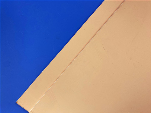
F4BTD350S is a glass fiber cloth reinforced PTFE high-frequency copper clad laminate filled with massive high thermal conductivity specialty ceramics, developed as a next-generation substrate material targeting circuits requiring low insertion loss and efficient heat dissipation. It acts as a fully interchangeable domestic replacement for imported high thermal conductivity RF laminates.
Combining ultra-low dielectric loss and premium heat transfer capacity, this material significantly enhances microwave power tolerance and supports stable long-term high-temperature operation, lowering equipment failure risks and overall maintenance costs. Meanwhile, its low thermal expansion coefficient, stable dimensional performance, high dielectric strength and superior insulation simplify PCB manufacturing processes, raise plated through-hole reliability, reduce soldering failures, optimize component matching and strengthen environmental adaptability.
With outstanding mechanical and physical properties, F4BTD350S laminate supports multi-layer, high-layer-count and backplane PCB production. It also delivers excellent processing performance when fabricating dense hole arrays and ultra-fine circuit traces via standard PTFE circuit manufacturing processes.
9.2 Core Laminate Features
- High thermal conductivity with ultra-low dielectric loss
- Boosted power bearing capacity and long-term operational reliability
- Temperature-stable dielectric constant with low TCDK
- Low thermal expansion coefficient for precise dimensional consistency
- Strong radiation resistance and low vacuum outgassing performance
- Minimal water absorption to lock consistent electrical performance
9.3 Application Fields for F4BTD350S CCL
- High power radio frequency circuit systems
- RF power amplifier modules
- Microwave and millimeter-wave antenna hardware
- Industrial heating electronic equipment
- Microwave passive devices: couplers, filters, power splitters
10.Datasheet
Product Characteristics |
Test Condition |
Unit |
F4BTD350S |
Electrical Properties |
|
|
|
Dielectric Constant (Typical Value) |
2 GHz |
— |
3.52 |
Dielectric Constant (Typical Value) |
10 GHz |
— |
3.5 |
Dielectric Constant Tolerance |
— |
— |
±0.07 |
Dielectric Constant (Design Value) |
10 GHz |
— |
3.62 |
Loss Factor (Typical Value) |
2 GHz |
— |
0.0012 |
Loss Factor (Typical Value) |
10 GHz |
— |
0.0016 |
Temperature Coefficient of Dielectric Constant |
-55℃ ~ 150℃ |
PPM/℃ |
-45 |
Peel Strength |
1 OZ copper foil |
N/mm |
>0.8 |
Volume Resistivity |
C96/23/95 |
MΩ·cm |
1×10¹¹ |
Surface Resistance |
C96/23/95 |
MΩ |
1×10¹² |
Electric Strength (Z-direction) |
5KW, 500V/s |
KV/mm |
25 |
Breakdown Voltage (Horizontal Direction) |
5KW, 500V/s |
KV |
38 |
Comparative Tracking Index (CTI) |
23℃ / 50% / 24H |
V |
600 |
Thermal & Mechanical Properties |
|
|
|
Coefficient of Thermal Expansion (X, Y direction) |
-55℃ ~ 288℃ |
ppm/℃ |
11, 10 |
Coefficient of Thermal Expansion (Z-direction) |
-55℃ ~ 288℃ |
ppm/℃ |
40 |
Thermal Decomposition Temperature (Td) |
5% mass loss |
℃ |
500 |
Flexural Strength (X, Y direction) |
Normal state |
MPa |
74, 64 |
Tensile Strength (X, Y direction) |
Normal state |
MPa |
48, 45 |
Flexural Modulus (X, Y direction) |
Normal state |
MPa |
7500, 7000 |
Dimensional Stability (X, Y direction) |
After etching and baking |
% |
0.08, 0.18 |
Thermal Stress |
260℃ / 10s / 3 times |
— |
No delamination |
Thermal Conductivity |
Z-direction |
W/(m·K) |
1.25 |
Specific Heat Capacity |
— |
J/g·℃ |
0.8 |
Physical Properties |
|
|
|
Density |
Normal temperature |
g/cm³ |
2.21 |
Long-term Service Temperature |
High & low temperature box |
℃ |
-55 ~ +260 |
Water Absorption |
20±2℃, 24 hours |
% |
0.05 |
Flame Retardancy |
— |
UL-94 |
V-0 |
Dielectric Layer Composition |
— |
— |
PTFE, glass fiber cloth, high thermal conductivity special ceramics |
11.Summary
F4BTD350S Double Sided High Frequency Circuit Board integrates high thermal conductivity, low signal loss and stable mechanical properties to satisfy high-power RF industrial electronic demands. Built on 0.508mm glass fiber ceramic PTFE core with Dk 3.5 and thermal conductivity of 1.25W/MK, this 0.6mm rigid circuit board adopts Immersion Gold surface finish and conforms to IPC-Class-2 standards for global supply. Equipped with low CTE, UL 94-V0 flame retardant grade and ultra-low moisture absorption, this substrate-based circuit board drastically improves heat dissipation efficiency and power load capacity, serving as an ideal circuit carrier for power amplifiers, microwave antennas, industrial heating equipment and all types of passive microwave component manufacturing.
Tags:F4BTD350S PCB, 0.6mm Double Sided F4BTD350S RF PCB, F4BTD350S Immersion Gold Circuit Board, High Thermal Conductivity F4BTD350S Laminate, IPC-Class-2 F4BTD350S High Frequency PCB, 0.6mm High Power Amplifier PCB, Ceramic Filled F4BTD350S PTFE Substrate, Industrial Microwave PCB