


 Home
Home
Why Choose Taconic RF-35TC PCB? Technical Comparison with Common RF PCB Materials
 January 16,2026
For engineers designing critical high-frequency, high-power circuits—where every 0.1 dB of loss directly impacts system efficiency and linearity—selecting the right PCB material is paramount. While standard FR-4 and common hydrocarbon-based RF laminates serve many applications, they fall short in demanding RF power scenarios.
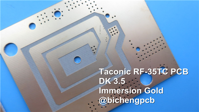
Taconic RF-35TC PCB is engineered specifically to bridge this performance gap, offering a superior combination of electrical stability, thermal management, and low loss.
1.Material Stability: No Oxidation or Drift
Many standard and mid-performance RF substrates, such as common hydrocarbon/ceramic laminates (e.g., RO4000® series analogs), can exhibit slight upward drift in dielectric constant (Dk) and dissipation factor (Df) over time or under thermal stress. In contrast, the PTFE-ceramic composite structure of the Taconic RF-35TC laminate is inherently inert. It will not oxidize, yellow, or experience meaningful electrical drift, ensuring predictable performance and longevity in field-deployed systems—a critical advantage for filters, couplers, and amplifiers requiring stable frequency response.
2.Superior Electrical & Thermal Performance: A Data-Driven Comparison
The advantage of Taconic RF-35TC PCBs becomes clear when examining key performance metrics against typical materials:
Parameter |
Standard FR-4 |
Common Hydrocarbon Laminate (e.g., RO4350B®) |
Taconic RF-35TC PCB Laminate |
Dielectric Constant (Dk) @ 10 GHz |
~4.3 (high & varies) |
3.48 ± 0.05 |
3.50 ± 0.05 |
Dissipation Factor (Df) @ 10 GHz |
~0.020 (very high) |
~0.0037 |
0.0011 |
Thermal Conductivity (W/m/K) |
~0.3 |
~0.6 |
0.80 |
Critical Performance Focus |
Cost, General Purpose |
Good RF Performance, Cost-Effective |
Ultra-Low Loss, High Power, Thermal Management |
Minimizing Insertion Loss: With an exceptionally low Df of 0.0011—approximately 3.4x lower than a common hydrocarbon laminate— Taconic RF-35TC PCB directly reduces conductor and dielectric losses. This translates to higher efficiency in power amplifiers and sharper roll-off in filters.
Managing Heat in High-Power Designs: The thermal conductivity of 0.80 W/m/K for Taconic RF-35TC is significantly higher than alternative RF PCBs. This property is crucial for dissipating heat from high-power transistors and transmission lines, preventing performance degradation and improving long-term reliability. Its bond with low-profile copper further enhances this thermal and electrical synergy.
3.Data Sheet of RF-35TC:
RF-35TC TYPICAL VALUES |
|||||
Property |
Test Method |
Unit |
Value |
Unit |
Value |
DK at 10 GHz |
IPC-650 2.5.5.5.1(modified) |
|
3.5 |
|
3.5 |
Tck(-30 to 120℃) |
IPC-650 2.5.5.5.1(modified) |
ppm |
24 |
ppm |
24 |
Df at 10 GHz |
IPC-650 2.5.5.5.1(modified) |
|
0.0011 |
|
0.0011 |
Dielectric Breakdown |
IPC-650 2.5.6(in-Plane,Two Pins in Oil) |
kV |
56.7 |
kV |
56.7 |
Dielectric Strength |
ASTM D 149(Through Plane) |
V/mil |
570 |
V/mm |
22,441 |
Arc Resistance |
IPC-650 2.5.1 |
Seconds |
304 |
Seconds |
304 |
Moisture Absorption |
IPC-650 2.6.2.1 |
% |
0.05 |
% |
0.05 |
Flexural Strength(MD) |
ASTM D 790/IPC-650 2.4.4 |
psi |
12,900 |
N/mm2 |
88.94 |
Flexural Strength(CD) |
ASTM D 790/IPC-650 2.4.4 |
psi |
11,700 |
N/mm2 |
80.67 |
Tensile Strength(MD) |
ASTM D 3039/IPC-TM-650 2.4.19 |
psi |
9,020 |
N/mm2 |
62.19 |
Tensile Strength(CD) |
ASTM D 3039/IPC-TM-650 2.4.19 |
psi |
7,740 |
N/mm2 |
53.37 |
Elongation at Break(MD) |
ASTM D 3039/IPC-TM-650 2.4.19 |
% |
1.89 |
N/mm |
1.89 |
Elongation at Break(CD) |
ASTM D 3039/IPC-TM-650 2.4.19 |
% |
1.7 |
% |
1.7 |
Young's Modulus(MD) |
ASTM D 3039/IPC-TM-650 2.4.19 |
psi |
667,000 |
N/mm2 |
4,599 |
Young's Modulus(CD) |
ASTM D 3039/IPC-TM-650 2.4.19 |
psi |
637,000 |
N/mm2 |
4,392 |
Poisson's Ratio(MD) |
ASTM D 3039/IPC-TM-650 2.4.19 |
|
0.18 |
|
0.18 |
Poisson's Ratio(CD) |
ASTM D 3039/IPC-TM-650 2.4.19 |
|
0.23 |
|
0.18 |
Compressive Modulus |
ASTM D 695(23℃) |
psi |
560,000 |
N/mm2 |
3,861 |
Flexural Strength(MD) |
ASTM D 790/IPC-650 2.4.4 |
psi |
1.46 x 10⁶ |
N/mm2 |
10,309 |
Flexural Strength(CD) |
ASTM D 790/IPC-650 2.4.4 |
psi |
1.50 x 10⁶ |
N/mm2 |
10,076 |
Peel Stength(½ oz.CVH) |
IPC-650 2.4.8(Thermal Stress.) |
Ibs./inch |
7 |
g/cm3 |
1.25 |
Thermal Conductivity(Unclad,125℃) |
ASTM F433(Guarded Heat Flow) |
W/(mK) |
0.6 |
W/(mK) |
0.6 |
Thermal Conductivity(C1/C1,125℃) |
ASTM F433(Guarded Heat Flow) |
W/(mK) |
0.92 |
W/(mK) |
0.92 |
Thermal Conductivity(CH/CH,125℃) |
ASTM F433(Guarded Heat Flow) |
W/(mK) |
0.87 |
W/(mK) |
0.87 |
Dimensional Stability(MD) |
IPC-650-2.4.39 Sec.5.4(After Etch) |
mils/in. |
0.23 |
mm/M |
0.23 |
Dimensional Stability(CD) |
IPC-650-2.4.39 Sec.5.4(After Etch) |
mils/in. |
0.64 |
mm/M |
0.64 |
Dimensional Stability(MD) |
IPC-650-2.4.39 Sec.5.5(Thermal Stress.) |
mils/in. |
-0.04 |
mm/M |
-0.04 |
Dimensional Stability(CD) |
IPC-650-2.4.39 Sec.5.5(Thermal Stress.) |
mils/in. |
0.46 |
mm/M |
0.46 |
Surface Resistivity |
IPC-650 2.5.17.1(after elevated temp.) |
Mohms |
8.33 x 10⁷ |
Mohms |
8.33 x 10⁷ |
Surface Resistivity |
IPC-650 2.5.17.1(after humidity) |
Mohms |
6.42 x 10⁷ |
Mohms |
6.42 x 10⁷ |
Volume Resistivity |
IPC-650 2.5.17.1(after elevated temp.) |
Mohms/cm |
5.19 x 10⁸ |
Mohms/cm |
5.19 x 10⁸ |
Volume Resistivity |
IPC-650 2.5.17.1(after humidity) |
Mohms/cm |
2.91 x 10⁸ |
Mohms/cm |
2.91 x 10⁸ |
CTE(X axis)(25-260℃) |
IPC-650 2.4.41/ASTM D 3386 |
ppm/℃ |
11 |
ppm/℃ |
11 |
CTE(Y axis)(25-260℃) |
IPC-650 2.4.41/ASTM D 3386 |
ppm/℃ |
13 |
ppm/℃ |
13 |
CTE(Z axis)(25-260℃) |
IPC-650 2.4.41/ASTM D 3386 |
ppm/℃ |
34 |
ppm/℃ |
34 |
Density |
ASTM D 792 |
g/cm3 |
2.35 |
g/cm3 |
2.35 |
Hardness |
ASTM D 2240(Shore D) |
|
79.1 |
|
79.1 |
Strain at Break(MD) |
ASTM D 790/IPC-650 2.4.4 |
% |
0.014 |
% |
0.014 |
Strain at Break(CD) |
ASTM D 790/IPC-650 2.4.4 |
% |
0.013 |
% |
0.013 |
Specific Heat |
ASTM E 1269-05,E 967-08,E968-02 |
j/(g℃) |
0.94 |
j/(g℃) |
0.94 |
Td(2% Weight Loss) |
IPC-650 2.4.24.6/TGA |
oF |
788 |
℃ |
420 |
Td(5% Weight Loss) |
IPC-650 2.4.24.6/TGA |
oF |
817 |
℃ |
436 |
4.Ideal Applications Demanding the Best
When your design cannot compromise, specifying a RF-35TC PCB provides a tangible performance edge. It is the substrate of choice for:
High-Power Amplifiers (e.g., base station, radar)
Low-Loss, High-Selectivity Filters & Couplers
Satellite Communication Payloads
Critical Aerospace & Defense RF Systems
5.Conclusion: The Clear Choice for Critical Designs
While other materials offer a balance of performance and cost, Taconic RF-35TC PCB is optimized for applications where minimal signal loss, stable electrical properties, and effective heat dissipation are non-negotiable. Its data-backed advantages in Df and thermal conductivity make it the definitive solution for pushing the limits of high-power, high-frequency circuit performance.
Founded in 2003, Shenzhen Bicheng Electronics Technology Co., Ltd is an established high frequency PCB supplier and exporter in Shenzhen, China, serving customers worldwide.
We are devoted to delivering high-frequency PCB products and solutions of the highest quality, along with customized service. Get in touch with us to start your project !
Visit https://www.bicheng-enterprise.com to learn more.