


 Home
Home
Automotive, Medical, and Aerospace PCBs: Key Differences and Decision Reference
 August 13,2026
A PCB that works perfectly in a smartphone could fail within months—or even hours—inside a car engine, a surgical robot, or a satellite orbiting Earth. Not because it's poorly made, but because it was designed to the wrong industry standard.
Automotive, medical, and aerospace PCBs differ not by a small margin, but in design philosophy, material systems, validation protocols, and documentation requirements. Here's a clear breakdown of what sets each industry apart—so you can make informed decisions for your specific application.
1.Automotive PCBs: Built for 15 Years of Zero-Defect Performance
Automotive electronics must survive one of the harshest environments on Earth: extreme temperature swings (-40°C to 150°C), constant vibration, moisture, salt spray, and electromagnetic interference—all while maintaining near-zero defect rates for a 10- to 15-year service life.
The automotive industry targets PPM (defects per million) below 50—meaning at most 1 defective board per 20,000 units.
Key Requirements
Requirement |
Automotive Specification |
Temperature Range |
-40°C to 150°C (engine compartment) |
Reliability Target |
PPM < 50 (near-zero defects) |
Primary Certification |
IATF 16949 |
IPC Addendum |
IPC-6012XA |
Common Features |
High-Tg (≥170°C), thick copper (≥3oz), HDI |
Failure Impact |
Vehicle safety, recalls, liability |
Materials and Design Considerations
Automotive PCBs typically use high-Tg materials to withstand thermal cycling. Thick copper is common for power circuits, and HDI (High-Density Interconnect) technology supports the miniaturization of ADAS (Advanced Driver Assistance Systems) and radar modules.
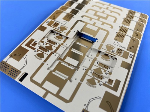
For automotive radar applications, Rogers RO3210 PCB is a popular choice due to its stable dielectric constant and low loss at high frequencies.
Impedance control is critical for high-speed signals in radar, LVDS, and Ethernet—50Ω single-ended or 100Ω differential impedance must be precisely maintained. EMI shielding is integrated to meet CISPR 25 standards.
Project Reference: In a 77GHz automotive radar project, we delivered a 12-layer board using a Rogers RO3210 + FR-4 hybrid stack-up. Critical RF traces achieved 100Ω ±5% differential impedance control, with dielectric constant tolerance held within ±0.05 at 10GHz. After 1,000 thermal cycles from -40°C to 140°C, impedance drift was less than ±3%. The design has passed validation and entered mass production.
Testing and Verification
Automotive PCBs undergo rigorous testing including temperature cycling, thermal shock, vibration and mechanical shock, salt spray, and HALT/HASS (Highly Accelerated Life Testing) to expose potential failure points before production.
Bottom line: Automotive PCBs prioritize reliability and consistency above all else. IATF 16949 certification and PPAP (Production Part Approval Process) Level 3 documentation are non-negotiable requirements.
2. Medical PCBs: Where Failure Is Not an Option
In medical devices, PCB failure can mean the difference between life and death. The stakes are higher, and so are the standards. Medical PCBs must demonstrate absolute reliability, full traceability, and—where patient contact is involved—biocompatibility—all under the framework of ISO 13485.
Key Requirements
Requirement |
Medical Specification |
Primary Certification |
ISO 13485 |
IPC Addendum |
IPC-6012EM |
Common Features |
Microvia, HDI, rigid-flex construction |
Failure Impact |
Patient harm, regulatory action |
Traceability |
Decades-long material and process records |
Materials and Design Considerations
Medical PCBs are often highly miniaturized, using microvia and HDI technology to fit complex electronics into wearables, implantables, and handheld diagnostics. Rigid-flex construction is common for devices requiring flexible connections in compact spaces.
Biocompatibility is a unique requirement: materials must be non-toxic and non-reactive to living tissue, following ISO 10993-1 standards where patient contact is possible.
Process Validation and Traceability
ISO 13485 demands rigorous process validation for special processes like laser drilling and copper filling of microvias. Lot-level traceability—linking materials, machines, test results, and personnel—is mandatory.
Bottom line: Medical PCBs demand ISO 13485 compliance, complete traceability, and documented process validation. Quality isn't just a goal—it's a regulatory requirement.
3. Aerospace and Military PCBs: Extreme Performance, Zero Compromise
Aerospace and military PCBs operate in the most unforgiving environments imaginable: vacuum, extreme temperature swings (-100°C to 120°C+), radiation, and high vibration. Once launched into orbit, replacement is impossible—so the boards must work perfectly, every time.
Key Requirements
Requirement |
Aerospace/Military Specification |
Temperature Range |
-100°C to 120°C+ |
Primary Certification |
AS9100 |
IPC Addendum |
IPC-6012DS |
Military Specification |
MIL-PRF-31032 |
Quality Class |
IPC Class 3A (highest reliability level) |
Common Features |
Outgassing control, low-Dk materials |
Failure Impact |
Mission failure, loss of equipment/life |
Traceability |
Full mission-level records |
Unique Challenges
Outgassing is a critical concern: in vacuum environments, trapped gases in materials can condense on sensitive components and interfere with operation. Materials with excellent thermal resistance and low outgassing properties are essential.
Radiation and debris pose additional risks. Ionizing radiation can degrade materials over time, and space debris collisions require boards to tolerate physical impacts—flex PCBs are increasingly used for their mechanical resilience.
Certifications and Standards
Aerospace PCBs must meet the most rigorous standards in the industry:
AS9100 – Aerospace quality management system with additional requirements for product safety, configuration management, and counterfeit parts prevention
IPC-6012DS – Enhanced qualification for aerospace and military rigid PCBs
MIL-PRF-31032 – Military performance specification for PCBs
IPC Class 3A – The highest IPC reliability class, mandatory for aerospace assemblies
Bottom line: Aerospace PCBs require the highest reliability standards, specialized materials to prevent outgassing, and certifications including AS9100 and IPC-6012DS.
4. How the Three Industries Compare
What kills a PCB in each industry?
Automotive: A thermal cycle that pushes past 150°C, a vibration that cracks a via, or a batch of material that drifts outside spec—any of these can trigger a recall of 100,000 vehicles.
Medical: Not a failure, but a missing record. If you can't prove which lot of material went into a specific device from 15 years ago, the regulator will shut down your production line—even if the board still works.
Aerospace: A trace of trapped gas released in vacuum, condensing on an optical lens. Or a single radiation-induced degradation that shifts a frequency by 0.5%. No repair truck is coming. The mission simply ends.
Typical Features
Automotive: High-Tg, thick copper (≥3oz), HDI, high-frequency materials
Medical: Microvia, HDI, rigid-flex, biocompatible materials (ISO 10993-1)
Aerospace: Low-outgassing, low-Dk materials, radiation-tolerant, flex for shock resistance
5. Final Thoughts
Choosing the right PCB for automotive, medical, or aerospace applications isn't just about technical specifications—it's about understanding the unique operational environment and regulatory framework each industry demands.
A board that meets automotive standards may not pass medical traceability requirements, and a medical-grade board may outgas in space.
The key is to identify which industry and which set of standards your application falls under, then verify materials, processes, testing, and documentation against the requirements outlined above.