


 Home
-
Newly shipped PCBs
-
Taconic TLY-5 2-Layer 125mil PCB – Low Dissipation Factor for 77GHz Automotive Radar
Home
-
Newly shipped PCBs
-
Taconic TLY-5 2-Layer 125mil PCB – Low Dissipation Factor for 77GHz Automotive Radar
Taconic TLY-5 2-Layer 125mil PCB – Low Dissipation Factor for 77GHz Automotive Radar
Printed Circuit Boards are custom-made products; the images and specifications provided are for reference only.
1.TLY-5 PCB Introduction
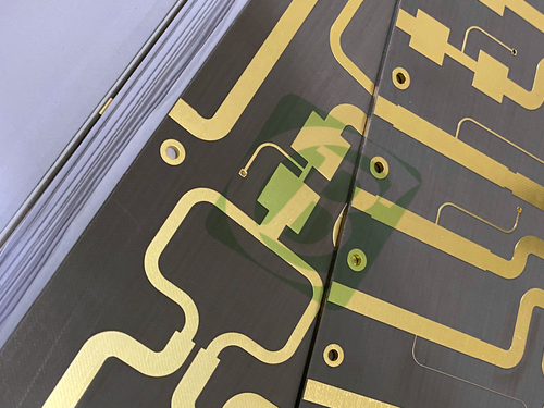
TLY-5 PCBs are constructed using ultra-lightweight woven fiberglass, delivering significantly superior dimensional stability compared to chopped fiber-reinforced PTFE composites. The woven fiberglass matrix of Taconic TLY-5 PCB creates a mechanically more stable laminate, which is well-suited for high-volume manufacturing processes and can effectively meet the needs of large-scale electronic component production scenarios. Meanwhile, leveraging its core advantage of a low dissipation factor, TLY-5 2-layer PCB not only enables successful deployment in 77 GHz automotive radar systems (such as adaptive cruise control and collision warning safety systems) but also supports other antenna devices operating at millimeter wave frequencies, providing reliable signal transmission guarantees for high-frequency communication and sensing fields.
2. Features
- Dielectric constant of 2.2 with tight tolerance 0.02 at 10 GHz/23°C
- 0.0009 loss tangent at 10GHz
- Density (specific gravity) of 2.19 g/cm3
- Moisture Absorption 0.02%
- CTE in X-axis of 26 ppm/°C, Y-axis of 15 ppm/°C and Z-axix of 217 ppm/°C
3. Benifits
- Dimensionally stable
- Lowest DF
- Low moisture absorption
- High copper peel strength
- Uniform & consistent DK
4. PCB Construction details:
- Base material: TLY-5
- Layer count: 2 layers
- Board dimensions: 106mm x 48.5 mm=1PCS, +/- 0.15mm
- Minimum Trace/Space: 7/7 mils
- Minimum Hole Size: 0.4mm
- No Blind vias.
- Finished board thickness: 3.2mm
- Finished Cu weight: 1oz (1.4 mils) outer layers
- Via plating thickness: 20 μm
- Surface finish: Immersion gold
- Top Silkscreen: No
- Bottom Silkscreen: No
- Top Solder Mask: No
- Bottom Solder Mask: No
- 100% Electrical test used prior to shipment
5. PCB Stackup: 2-layer rigid PCB
Copper_layer_1 - 35 μm
TLY-5 - 3.175 mm (125mil)
Copper_layer_2 - 35 μm
6. PCB Statistics:
Components: 39
Total Pads: 136
Thru Hole Pads: 74
Top SMT Pads: 62
Bottom SMT Pads: 0
Vias: 97
Nets: 2
7. Type of artwork supplied: Gerber RS-274-X
8. Accepted standard: IPC-Class-2
9. Availability: worldwide
10. Key Advantages of TLY-5 Laminate:
TLY-5 PCB substrate is a woven fiberglass-reinforced PTFE laminate engineered for high-frequency RF and microwave applications. TLY-5 high-frequency material offers a stable dielectric constant of 2.20 ± 0.02 and an ultra-low dissipation factor of 0.0009 at 10 GHz, ensuring minimal insertion loss and excellent signal integrity over a broad frequency range. Its low moisture absorption rate of below 0.02% provides superior dimensional stability and consistent electrical performance in humid environments. TLY-5 PCB material also features a low Z-axis coefficient of thermal expansion, which enhances plated through-hole reliability during thermal cycling. With a density of 2.0 g/cm³, TLY-5 PCB laminate is lightweight and well-suited for aerospace, defense, and 5G millimeter-wave applications. TLY-5 microwave material offers excellent copper peel strength and supports hybrid multilayer constructions, making it a versatile and cost-effective solution for demanding high-reliability circuit designs.
11. Some Typical Applications:
- Automotive Radar
- Satellite/Cellular Communications
- Power Amplifiers
- LNBs, LNAs, LNCs
- Aerospace
- Ka, E and W band Applications
12.Appendix: Typical Value of TLY-5
| Property | Test Method | Unit | Value | Unit | Value |
| DK at 10 GHz | IPC-650 2.5.5.5 | 2.2 | 2.2 | ||
| Df at 10 GHz | IPC-650 2.5.5.5 | 0.0009 | 0.0009 | ||
| Moisture Absorption | IPC-650 2.6.2.1 | % | 0.02 | % | 0.02 |
| Dielectric Breakdown | IPC-650 2.5.6 | kV | >45 | kV | >45 |
| Dielectric Strength | ASTM D 149 | V/mil | 2,693 | V/mil | 106,023 |
| Volume Resistivity | IPC-650 2.5.17.1(after elevated temp.) | Mohms/cm | 1010 | Mohms/cm | 1010 |
| Volume Resistivity | IPC-650 2.5.17.1(after humidity) | Mohms/cm | 1010 | Mohms/cm | 109 |
| Surface Resistivity | IPC-650 2.5.17.1(after elevated temp.) | Mohms | 108 | Mohms | 108 |
| Surface Resistivity | IPC-650 2.5.17.1(after humidity) | Mohms | 108 | Mohms | 108 |
| Flex Strength(MD) | IPC-650 2.4.4 | psi | 14,057 | N/mm2 | 96.91 |
| Flex Strength(CD) | IPC-650 2.4.4 | psi | 12,955 | N/mm2 | 89.32 |
| Peel Stength(½ oz.ed copper) | IPC-650 2.4.8 | Ibs./inch | 11 | N/mm | 1.96 |
| Peel Stength(1 oz.CL1 copper) | IPC-650 2.4.8 | Ibs./inch | 16 | N/mm | 2.86 |
| Peel Stength(1 oz..CV1 copper) | IPC-650 2.4.8 | Ibs./inch | 17 | N/mm | 3.04 |
| Peel Stength | IPC-650 2.4.8(after elevated temp.) | Ibs./inch | 13 | N/mm | 2.32 |
| Young's Modulus(MD) | ASTM D 3039/IPC-650 2.4.19 | psi | 1.4 x 10⁶ | N/mm2 | 9.65 x 10³ |
| Poisson's Ratio(MD) | ASTM D 3039/IPC-650 2.4.19 | 0.21 | 0.21 | ||
| Thermal Conductivity | ASTM F 433 | W/M*K | 0.22 | W/M*K | 0.22 |
| Dimensional Stability(MD,10mil) | IPC-650 2.4.39(avg.after bake&thermal stress) | mils/inch | -0.038 | -0.038 | |
| Dimensional Stability(CD,10mil) | IPC-650 2.4.39(avg.after bake&thermal stress) | mils/inch | -0.031 | -0.031 | |
| Density(Specific Gravity) | ASTM D 792 | g/cm3 | 2.19 | g/cm3 | 2.19 |
| CTE(X axis)(25-260℃) | ASTM D 3386(TMA) | ppm/℃ | 26 | ppm/℃ | 26 |
| CTE(Y axis)(25-260℃) | ASTM D 3386(TMA) | ppm/℃ | 15 | ppm/℃ | 15 |
| CTE(Z axis)(25-260℃) | ASTM D 3386(TMA) | ppm/℃ | 217 | ppm/℃ | 217 |
| NASA Outgassing(% TML) | 0.01 | 0.01 | |||
| NASA Outgassing(% CVCM) | 0.01 | 0.01 | |||
| NASA Outgassing(% WVR) | 0.00 | 0.00 | |||
| UL-94 Flammability Rating | UL-94 | V-0 | V-0 |