

 Home
-
Newly shipped PCBs
-
Rogers TMM10 2-Layer PCB built on 15mil TMM10 Laminate for Reliable Thermoset Microwave Solution
Home
-
Newly shipped PCBs
-
Rogers TMM10 2-Layer PCB built on 15mil TMM10 Laminate for Reliable Thermoset Microwave Solution
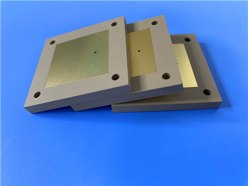
Rogers TMM10 2-Layer PCB built on 15mil TMM10 Laminate for Reliable Thermoset Microwave Solution
Printed Circuit Boards are custom-made products; the images and specifications provided are for reference only.
1. Rogers TMM10 PCB Overview
Rogers TMM10 high-frequency PCB is a high-performance 2-layer rigid printed circuit board, engineered with TMM10 thermoset microwave material as its core substrate. Rogers TMM10 PCB combines the advantages of both PTFE and ceramic-based substrates, while overcoming their limitations in mechanical properties and production complexity. Designed for high-frequency microwave and RF applications, TMM10 PCB delivers consistent electrical performance, excellent dimensional stability, and easy fabrication, making it a cost-effective and reliable choice for diverse industrial scenarios worldwide.
2. Core Features of Rogers TMM10 PCB
- Dielectric Constant (Dk): 9.20 +/- 0.230
- Dissipation Factor: 0.0022 at 10 GHz
- Thermal Coefficient of Dk: -38 ppm/°K
- Coefficient of Thermal Expansion (CTE): 21 ppm/K (X), 21 ppm/K (Y), 20 ppm/K (Z), perfectly matched to copper
- Decomposition Temperature (Td): 425 °C (TGA)
- Thermal Conductivity: 0.76 W/mK
- Substrate Thickness Range: 0.0015 to 0.500 inches +/- 0.0015”
3. Key Advantages of TMM10 High Frequency PCB
- Superior Mechanical Performance: Resists creep and cold flow, ensuring long-term structural integrity even in harsh operating environments
- Chemical Resistance: Tolerant to process chemicals, minimizing damage during PCB fabrication and assembly
- Simplified Fabrication: Eliminates the need for sodium napthanate treatment prior to electroless plating, reducing production steps and costs
- Reliable Wire-Bonding: Based on thermoset resin, the substrate does not soften when heated, preventing pad lifting or deformation during wire bonding
4. Detailed PCB Construction Parameters
Construction Item |
Specification |
Base material |
TMM10 |
Layer count |
Double sided |
Board dimensions |
76mm x 118mm = 1PCS, +/- 0.15mm |
Minimum Trace/Space |
4/6 mils |
Minimum Hole Size |
0.35mm |
Blind vias |
No |
Finished board thickness |
0.5mm |
Finished Cu weight (outer layers) |
1 oz (1.4 mils) |
Via plating thickness |
20 μm |
Surface finish |
ENEPIG |
Top Silkscreen |
White |
Bottom Silkscreen |
No |
Top Solder Mask |
Green |
Bottom Solder Mask |
No |
Pre-shipment Electrical Test |
100% Electrical test used |
5. PCB Stackup Configuration
2-layer rigid PCB, with the following layer structure (from top to bottom):
- Copper_layer_1 - 35 μm
- Rogers TMM10 Core - 0.381 mm (15mil)
- Copper_layer_2 - 35 μm
6. PCB Technical Statistics
- Components: 34 | Total Pads: 56 | Thru Hole Pads: 32
- Top SMT Pads: 24 | Bottom SMT Pads: 0 | Vias: 24 | Nets: 2
7. Artwork Format Supplied
Gerber RS-274-X, the industry-standard format for PCB fabrication, ensuring compatibility with most manufacturing equipment.
8. Quality Assurance Standard
Complies with IPC-Class-2 standards, guaranteeing consistent quality, reliability, and performance for commercial and industrial applications.
9. Global Availability
Available worldwide, with reliable supply chains to support global customers’ production needs and timely delivery.
10. Typical Application Scenarios
- Chip testers and semiconductor testing equipment
- Dielectric polarizers for microwave systems
- Satellite communication systems and related components
- GPS antennas, patch antennas, and other wireless communication devices
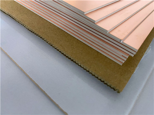
11. Rogers TMM Series CCL Introduction
Rogers TMM series thermoset microwave CCL (Copper Clad Laminate) is a high-performance composite material, composed of ceramic, hydrocarbon, and thermoset polymer. It is specifically designed for high-reliability stripline and microstrip applications, offering a perfect balance of electrical and mechanical properties. Unlike traditional PTFE/ceramic laminates, TMM CCL combines their key advantages without requiring specialized production techniques, making it more cost-effective and easier to fabricate.
11.1 Key Properties of TMM Series CCL
- Exceptionally low thermal coefficient of dielectric constant (typically less than 30 ppm/°C), ensuring stable electrical performance across temperature fluctuations
- Isotropic CTE closely matched to copper, enhancing plated through-hole reliability and minimizing etch shrinkage for high-precision PCB designs
- Thermal conductivity approximately twice that of traditional PTFE/ceramic laminates, facilitating efficient heat dissipation in high-power applications
- Thermoset resin base, maintaining rigidity when heated to enable reliable wire bonding without pad lifting or substrate deformation
- Resistant to etchants and solvents used in PCB production, compatible with all common printed circuit board processes
11.2 Available Specifications of TMM Series CCL
- Wide range of dielectric constants to suit diverse high-frequency application needs
- Copper foil weights: 1/2 oz/ft² to 2 oz/ft²
- Can be bonded directly to brass or aluminum plates for additional application flexibility
- Substrate thickness range: 0.015” to 0.500”, catering to various design requirements
11.3 Features & Benefits of TMM Series CCL
- Wide Range of Dielectric Constants: Ideal for single-material systems across a broad spectrum of high-frequency applications, reducing design complexity.
- Exceptional Mechanical Properties: Resists creep and cold flow, ensuring long-term structural stability in harsh operating conditions.
- Copper-Matched CTE: Delivers high reliability of plated through-holes, minimizing deformation and improving PCB durability.
- Chemical Resistance: Reduces damage during fabrication and assembly processes, lowering production defects and costs.
- Thermoset Resin Base: Enables reliable wire bonding, eliminates the need for specialized production techniques, and TMM10i laminates can directly replace alumina substrates for cost savings.
12.DataSheet
Properties |
Typical Value |
Direction |
Units |
Test Conditions |
Test Method |
Electrical Properties |
|
|
|
|
|
Dielectric Constant (process) |
9.20 ± 0.230 |
Z |
– |
10 GHz |
IPC-TM-650 2.5.5.5 |
Dielectric Constant (design) |
9.8 |
– |
– |
8 GHz – 40 GHz |
Differential Phase Length Method |
Dissipation Factor (process) |
0.0022 |
Z |
– |
10 GHz |
IPC-TM-650 2.5.5.5 |
Thermal Coefficient of Dielectric Constant |
-38 |
– |
ppm/°K |
-55 to +125°C |
IPC-TM-650 2.5.5.5 |
Insulation Resistance |
>2000 |
– |
Gohm |
C/96/60/95 |
ASTM D257 |
Volume Resistivity |
2×10⁸ |
– |
MΩ·cm |
– |
ASTM D257 |
Surface Resistivity |
4×10⁷ |
– |
MΩ |
– |
ASTM D257 |
Electrical Strength (Dielectric Strength) |
285 |
Z |
V/mil |
– |
IPC-TM-650 2.5.6.2 |
Thermal Properties |
|
|
|
|
|
Decomposition Temperature (Td) |
425 |
– |
°C |
TGA |
ASTM D3850 |
Coefficient of Thermal Expansion – x |
21 |
X |
ppm/K |
0 to 140°C |
ASTM E 831, IPC-TM-650 2.4.41 |
Coefficient of Thermal Expansion – y |
21 |
Y |
ppm/K |
0 to 140°C |
ASTM E 831, IPC-TM-650 2.4.41 |
Coefficient of Thermal Expansion – z |
20 |
Z |
ppm/K |
0 to 140°C |
ASTM E 831, IPC-TM-650 2.4.41 |
Thermal Conductivity |
0.76 |
Z |
W/m/K |
80°C |
ASTM C518 |
Mechanical Properties |
|
|
|
|
|
Copper Peel Strength after Thermal Stress |
5.0 (0.9) |
X,Y |
lb/inch (N/mm) |
After solder float, 1 oz. EDC |
IPC-TM-650 2.4.8 |
Flexural Strength (MD/CMD) |
13.62 |
X,Y |
kpsi |
A |
ASTM D790 |
Flexural Modulus (MD/CMD) |
1.79 |
X,Y |
Mpsi |
A |
ASTM D790 |
General Properties |
|
|
|
|
|
Moisture Absorption (1.27 mm / 0.050”) |
0.09 |
– |
% |
D/24/23 |
ASTM D570 |
Moisture Absorption (3.18 mm / 0.125”) |
0.20 |
– |
% |
D/24/23 |
ASTM D570 |
Specific Gravity |
2.77 |
– |
– |
A |
ASTM D792 |
Specific Heat Capacity |
0.74 |
– |
J/g/K |
A |
Calculated |
Lead-Free Process Compatible |
YES |
– |
– |
– |
– |
13.Summary
Rogers TMM10 2-Layer RF circuit board is a high-performance, cost-effective solution tailored for microwave and RF applications. Leveraging the advanced properties of Rogers TMM10 thermoset substrate, this 0.5mm thick double-sided PCB offers stable dielectric performance, excellent dimensional stability, and simplified fabrication. Compliant with IPC-Class-2 standards, globally available, and equipped with ENEPIG surface finish, it meets the rigorous requirements of chip testers, satellite communication systems, and wireless antennas, providing reliable performance and long-term value for volume production.