


 Home
-
Newly shipped PCBs
-
Rogers RT/duroid 6006 2-Layer Microwave Printed Circuit Board--10mil RT/duroid 6006 Low Loss Laminate with Immersion Silver
Home
-
Newly shipped PCBs
-
Rogers RT/duroid 6006 2-Layer Microwave Printed Circuit Board--10mil RT/duroid 6006 Low Loss Laminate with Immersion Silver
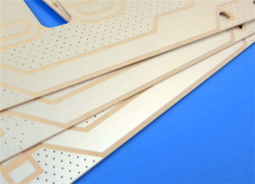
Rogers RT/duroid 6006 2-Layer Microwave Printed Circuit Board--10mil RT/duroid 6006 Low Loss Laminate with Immersion Silver
Printed Circuit Boards are custom-made products; the images and specifications provided are for reference only.
1. Rogers RT/duroid 6006 PCB Introduction
Rogers RT/duroid 6006 high frequency PCB is a high-performance microwave circuit board built on advanced ceramic-PTFE composite dielectric materials. Optimized for high-precision RF and microwave applications, this Rogers 2-layer rigid PCB features a high and stable dielectric constant, enabling miniaturized circuit design while maintaining ultra-low signal loss performance. It is perfectly suited for X-band and lower frequency wireless microwave systems with strict requirements for signal stability and compact board size.
Rogers RT/duroid 6006 dielectric material adopts a professional ceramic-filled PTFE composite formula, delivering extremely tight dielectric constant tolerance and precise thickness consistency. This superior controllability ensures highly repeatable electrical performance for mass-produced microwave circuits. With ultra-low moisture absorption and excellent thermo-mechanical stability, the board retains stable electrical parameters in complex and variable working environments.
Available with standard or reverse-treated electrodeposited copper foil cladding on both sides, RT/duroid 6006 PCB supports diversified copper thickness specifications and flexible structural customization. It features straightforward fabrication processes and reliable plated through-hole performance, providing a stable and high-yield solution for multi-layer microwave circuit design and industrial mass production.
2. RT/duroid 6006 PCB Material Features
- Premium Material Construction: High-performance ceramic-PTFE composite dielectric structure for microwave-grade circuit applications
- Stable Dielectric Constant: DK 6.15 +/- 0.15 tested at 10 GHz / 23°C, supporting circuit miniaturization design
- Ultra-Low Dissipation Factor: Df 0.0027 at 10 GHz / 23°C to minimize microwave signal attenuation
- Extreme Thermal Stability: Thermal decomposition temperature TDA higher than 500°C
- Low Moisture Absorption Rate: Only 0.05%, eliminating electrical performance drift caused by humidity changes
- Precise CTE Parameters: X-axis 47 ppm/°C, Y-axis 34 ppm/°C, Z-axis 117 ppm/°C for controllable thermal expansion
- Dual Foil Cladding Option: Compatible with standard and reverse-treated electrodeposited copper foil for diverse design demands
- Strict Dk and thickness tolerance control for consistent batch production performance
3. Key Product Benefits
- High dielectric constant effectively reduces circuit board footprint, supporting compact and miniaturized microwave device design
- Ultra-low loss dielectric properties ensure minimal signal attenuation, ideal for X-band and below microwave frequency operation
- Strict dielectric constant and dimensional thickness control deliver highly consistent and repeatable circuit electrical performance
- Extremely low moisture absorption avoids signal loss fluctuation and parameter deviation in humid operating conditions
- Optimized Z-axis expansion performance guarantees reliable plated through-hole structure for multilayer microwave PCB construction
- Excellent thermo-mechanical stability prevents board deformation and performance degradation during processing and long-term operation
- Flexible copper foil cladding and thickness specifications meet customized microwave circuit design and production requirements
4. PCB Construction Details
Item |
Specification |
Base Material |
Rogers RT/duroid 6006 |
Layer Count |
2-Layer Rigid PCB |
Board Dimensions |
134.8mm x 78.65mm (2 Types, 2PCS), Tolerance: +/- 0.15mm |
Minimum Trace / Space |
5/6 mils |
Minimum Hole Size |
0.3mm |
Blind Vias |
Not Allowed |
Finished Board Thickness |
0.4mm |
Finished Outer Copper Weight |
1 oz (1.4 mils) |
Via Plating Thickness |
20 μm |
Surface Finish |
Immersion Silver |
Top Silkscreen |
None |
Bottom Silkscreen |
None |
Top Solder Mask |
None |
Bottom Solder Mask |
None |
Pre-Shipment Test |
100% Electrical Test |
5. PCB Stackup Structure
This 2-layer rigid RT/duroid 6006 high frequency PCB adopts a flat and stable composite stackup structure with precise industrial-standard thickness configuration:
- Copper Layer 1: 35 μm
- Rogers RT/duroid 6006 Core Dielectric: 0.254mm (10mil)
- Copper Layer 2: 35 μm
6. PCB Statistical Parameters
- Total Components: 46
- Total Pads: 64
- Thru Hole Pads: 26
- Top SMT Pads: 38
- Bottom SMT Pads: 0
- Total Vias: 41
- Total Nets: 2
7. Manufacturing Artwork & Quality Standard
- Artwork Format: Gerber RS-274-X
- Industry Quality Standard: IPC-Class-2
8. Global Availability
This custom Rogers RT/duroid 6006 2-layer microwave PCB supports worldwide supply and global shipping services. It is widely available for procurement by microwave communication enterprises, aerospace equipment manufacturers and high-frequency RF circuit design teams across the globe.
9. Typical Applications
- Wireless antenna systems: High-performance patch antenna devices
- Aerospace communication: Professional satellite communication system circuits
- RF power devices: Microwave power amplifier circuit boards
- Aviation safety equipment: Aircraft collision avoidance system modules
- Radar detection devices: Ground radar warning system microwave circuits
10. Rogers RT/duroid 6006 Copper Clad Laminate Knowledge
10.1 Product Overview
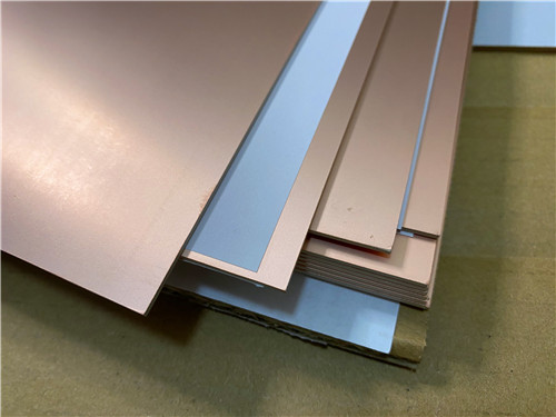
Rogers RT/duroid 6006 laminate is a professional ceramic-PTFE composite dielectric material tailored for high-frequency and microwave circuit applications. Featuring a high and tightly controlled dielectric constant, RT/duroid 6006 material enables effective miniaturization of microwave circuit dimensions while maintaining ultra-low signal loss characteristics. It supports multiple standard dielectric thickness specifications and dual-sided copper cladding with optional copper foil types, providing extreme flexibility for customized microwave PCB design.
10.2 Dielectric Performance & Frequency Stability
RT/duroid 6006 circuit material delivers stable electrical performance across microwave frequency bands. With a Dk value of 6.15±0.15 and an ultra-low Df of 0.0027 at 10 GHz, it ensures minimal signal attenuation and excellent signal integrity for X-band and lower-frequency microwave operation. Benefiting from strict dielectric constant and thickness tolerance control, RT/duroid 6006 material achieves highly consistent electrical repeatability in batch production, avoiding performance differences between individual circuit boards.
10.3 Thermo-Mechanical Stability
RT/duroid 6006 high-frequency laminate features reliable thermal stability with a thermal decomposition temperature exceeding 500°C, adapting to high-temperature PCB processing and long-term high-power operation. Its low moisture absorption rate of 0.05% prevents electrical parameter drift caused by environmental humidity changes. Matched with professional multi-axis CTE parameters, the material maintains stable structural performance and ensures reliable plated through-hole quality for multilayer microwave PCB structures.
10.4 Fabrication Flexibility & Customization
RT/duroid 6006 microwave material supports standard microwave PCB fabrication processes, compatible with both standard and reverse-treated electrodeposited copper foil cladding. It provides multiple optional dielectric thicknesses and copper foil weight specifications, allowing designers to flexibly adjust circuit structure according to frequency and power demands. The material features excellent processing adaptability and stable usability, greatly improving production yield for high-precision microwave circuits.
10.5 Core Material Advantages
- High dielectric constant supports compact circuit design and equipment miniaturization
- Ultra-low dissipation factor guarantees low-loss transmission for microwave signals
- Precise Dk and thickness tolerance ensures consistent batch circuit performance
- Superior humidity resistance stabilizes electrical performance in complex environments
- Reliable thermal mechanical properties support multilayer board fabrication
- Diversified copper cladding and thickness options meet customized design needs
10.6 Material Application Scenarios
- High-precision patch antenna and microwave antenna systems
- Satellite communication transceiver circuit modules
- Microwave power amplifier and RF signal processing circuits
- Aviation collision avoidance and safety monitoring equipment
- Ground radar warning and microwave detection systems
11. Datasheet
Property |
Typical Values |
Direction |
Units |
Test Conditions |
Test Method |
Dielectric Constant εr (Process) |
6.15 ± 0.15 |
Z |
-- |
10 GHz, 23°C |
IPC-TM-650 2.5.5.5 Clamped stripline |
Dielectric Constant εr (Design) |
6.45 |
Z |
-- |
8 GHz - 40 GHz |
Differential Phase Length Method |
Dissipation Factor, tan δ |
0.0027 |
Z |
-- |
10 GHz/A |
IPC-TM-650 2.5.5.5 |
Thermal Coefficient of ε |
-410 |
Z |
ppm/°C |
-50 to 170°C |
IPC-TM-650 2.5.5.5 |
Surface Resistivity |
7 × 10^7 |
-- |
Mohm |
A |
IPC 2.5.17.1 |
Volume Resistivity |
2 × 10^7 |
-- |
Mohm•cm |
A |
IPC 2.5.17.1 |
Tensile Young’s Modulus |
627 (91) |
X |
MPa (kpsi) |
A |
ASTM D638 (0.1/min. strain rate) |
Tensile Young’s Modulus |
517 (75) |
Y |
MPa (kpsi) |
A |
ASTM D638 (0.1/min. strain rate) |
Tensile Ultimate Stress |
20 (2.8) |
X |
MPa (kpsi) |
A |
ASTM D638 |
Tensile Ultimate Stress |
17 (2.5) |
Y |
MPa (kpsi) |
A |
ASTM D638 |
Tensile Ultimate Strain |
12 to 13 |
X |
% |
A |
ASTM D638 |
Tensile Ultimate Strain |
4 to 6 |
Y |
% |
A |
ASTM D638 |
Compressive Young’s Modulus |
1069 (155) |
Z |
MPa (kpsi) |
A |
ASTM D695 (0.05/min. strain rate) |
Compressive Ultimate Stress |
54 (7.9) |
Z |
MPa (kpsi) |
A |
ASTM D695 |
Compressive Ultimate Strain |
33 |
Z |
% |
-- |
ASTM D695 |
Flexural Modulus |
2634 (382) |
X |
MPa (kpsi) |
A |
ASTM D790 |
Flexural Modulus |
1951 (283) |
Y |
MPa (kpsi) |
A |
ASTM D790 |
Flexural Ultimate Stress |
38 (5.5) |
X,Y |
MPa (kpsi) |
A |
ASTM D790 |
Deformation under Load |
0.33 |
Z |
% |
24 hr / 50°C / 7MPa |
ASTM D261 |
Deformation under Load |
2.10 |
Z |
% |
24 hr / 150°C / 7 MPa |
ASTM D261 |
Moisture Absorption |
0.05 |
-- |
% |
D48/50°C, 0.050” (1.27mm) thick |
IPC-TM-650, 2.6.2.1 |
Density |
2.7 |
-- |
g/cm3 |
-- |
ASTM D792 |
Thermal Conductivity |
0.49 |
-- |
W/m/°K |
80°C |
ASTM C518 |
Coefficient of Thermal Expansion |
47 |
X |
ppm/°C |
23°C / 50% RH |
IPC-TM-650 2.4.41 |
Coefficient of Thermal Expansion |
34, 117 |
Y,Z |
ppm/°C |
23°C / 50% RH |
IPC-TM-650 2.4.41 |
Decomposition Temperature (Td) |
500 |
-- |
°C |
TGA |
ASTM D3850 |
Specific Heat |
0.97 (0.231) |
-- |
J/g/K (BTU/lb/°F) |
-- |
Calculated |
Copper Peel Strength |
14.3 (2.5) |
-- |
pli (N/mm) |
after solder float |
IPC-TM-650 2.4.8 |
Flammability Rating |
V-0 |
-- |
-- |
-- |
UL94 |
Lead-Free Process Compatible |
Yes |
-- |
-- |
-- |
-- |
12. Summary
Rogers RT/duroid 6006 2-Layer microwave PCB is a high-stability, miniaturized circuit solution for professional microwave and RF applications. Adopting premium ceramic-PTFE composite dielectric material, it features high controllable dielectric constant, ultra-low signal loss, low moisture absorption and excellent thermo-mechanical stability. With 0.4mm board thickness, immersion silver surface finish and strict IPC-Class-2 manufacturing standards, this Rogers PCB delivers consistent and reliable performance for patch antennas, satellite communication systems, power amplifiers and aviation radar devices, serving as an ideal high-frequency circuit substrate for industrial and aerospace microwave equipment.
Tags:Rogers RT/duroid 6006 PCB, 2-Layer 0.4mm Microwave PCB, Immersion Silver High Frequency PCB, Low Loss Ceramic PTFE PCB, High DK Microwave Circuit Board, IPC Class 2 RF PCB, Patch Antenna PCB, Satellite Communication PCB, Radar Warning System PCB, X-Band Low Loss PCB