


 Home
-
Newly shipped PCBs
-
Rogers RO4003C and 370HR Hybrid High Frequency PCB 10-Layer 1.618mm Controlled Impedance PCB with Blind Via and Resin Plugged Hole
Home
-
Newly shipped PCBs
-
Rogers RO4003C and 370HR Hybrid High Frequency PCB 10-Layer 1.618mm Controlled Impedance PCB with Blind Via and Resin Plugged Hole
Rogers RO4003C and 370HR Hybrid High Frequency PCB 10-Layer 1.618mm Controlled Impedance PCB with Blind Via and Resin Plugged Hole
Printed Circuit Boards are custom-made products; the images and specifications provided are for reference only.
1. RO4003C and 370HR PCB Product Overview
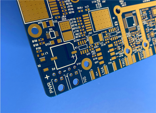
This custom 10-Layer 1.618mm hybrid high frequency PCB is laminated with 8mil RO4003C laminate and 370HR materials, specially designed for high frequency RF circuits and precision controlled impedance scenarios. Rogers RO4003C and 370HR circuit board adopts 1oz finished copper for outer layers, and 1oz plus 0.5oz Yin-Yang copper for inner layers, with overall lamination thickness of 1.618mm. Both top and bottom layers adopt blue solder mask with white legend, and the surface is finished with 135% to 150% immersion gold.It supports strict impedance control: Top layer trace width 12.2mil for 50 Ohm; Layer 3 trace width 3.5mil and spacing 5.5mil for 80 Ohm.Process features include blind via L1-L2, L9-L10, L7-L10 and full resin plugged hole. Board dimension is 132mm x 144mm per piece, ideal for wireless base station, RF microwave and automotive radar applications.
2.PCB Specifications
Item |
Specification Parameter |
Board Structure |
10-Layer multilayer PCB |
Dielectric Material |
8mil RO4003C and 370HR hybrid laminate |
Outer Layer Copper |
1oz finished copper |
Inner Layer Copper |
1oz / 0.5oz Yin-Yang copper |
Lamination Thickness |
1.618mm |
Solder Mask |
Top blue solder mask with white legend, bottom blue solder mask with white legend |
Surface Treatment |
135%–150% Immersion Gold |
Board Size |
132mm x 144mm per piece |
Controlled Impedance |
Top: 12.2mil trace width, 50 Ohm; Layer 3: 3.5mil width / 5.5mil spacing, 80 Ohm |
Special Process |
Blind via L1-L2, L9-L10, L7-L10; Resin plugged hole |
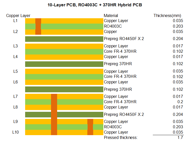
3. PCB Stackup Structure
This 10-Layer 1.618mm RO4003C and 370HR hybrid PCB adopts symmetrical stackup for stable high frequency and impedance performance.
4. RO4003C Laminate Introduction
RO4003C belongs to RO4000 series hydrocarbon ceramic high frequency laminates, not PTFE based material. It is developed for high frequency low loss and cost-sensitive mass production applications above 500MHz.It features low dielectric tolerance, low insertion loss and stable dielectric constant across wide frequency range. The temperature coefficient of dielectric constant is extremely low, suitable for broadband circuits, controlled impedance lines and filter design.With high Tg over 280°C and low thermal expansion coefficient close to copper, RO4003C delivers excellent dimensional stability and reliable plated through hole performance under thermal shock. It can be processed with standard FR4 manufacturing processes without special via etching treatment, supporting automated production and CAF resistance.
4.1 RO4003C Applications
Cellular Base Station Antennas and Power Amplifiers
RF Identification Tags
Automotive Radar and Sensors
LNB's for Direct Broadcast Satellites
4.2 RO4003C Datasheet
Property Category |
Property Name |
RO4003C Typical Value |
Direction |
Units |
Test Conditions |
Test Method |
Electrical Properties |
Dielectric Constant (εr, Process) |
3.38 ± 0.05 |
Z |
- |
10 GHz/23°C |
IPC-TM-650 2.5.5.5 |
|
Dielectric Constant (εr, Design, Clamped Stripline) |
3.55 |
Z |
- |
8 to 40 GHz |
Differential Phase Length Method |
|
Dissipation Factor (tan δ) |
0.0027 / 0.0021 |
Z |
- |
10 GHz/23°C, 2.5 GHz/23°C |
IPC-TM-650 2.5.5.5 |
|
Thermal Coefficient of Dielectric Constant (εr) |
+40 |
Z |
ppm/°C |
-50°C to 150°C |
IPC-TM-650 2.5.5.5 |
|
Volume Resistivity |
1.7 × 10¹⁰ |
- |
MΩ•cm |
Condition A |
IPC-TM-650 2.5.17.1 |
|
Surface Resistivity |
4.2 × 10⁹ |
- |
MΩ |
Condition A |
IPC-TM-650 2.5.17.1 |
|
Electrical Strength |
31.2 (780) |
Z |
kV/mm (V/mil) |
0.51mm (0.020") |
IPC-TM-650 2.5.6.2 |
Mechanical Properties |
Tensile Modulus (Young’s Modulus) |
19,650 (2,850) / 19,450 (2,821) |
X / Y |
MPa (ksi) |
RT (Room Temperature) |
ASTM D638 |
|
Tensile Strength |
139 (20.2) / 100 (14.5) |
X / Y |
MPa (ksi) |
RT (Room Temperature) |
ASTM D638 |
|
Flexural Strength |
276 (40) |
- |
MPa (kpsi) |
- |
IPC-TM-650 2.4.4 |
|
Dimensional Stability |
<0.3 |
X, Y |
mm/m (mils/inch) |
After etch + E2/150°C |
IPC-TM-650 2.4.39A |
|
Copper Peel Strength |
1.05 (6.0) |
- |
N/mm (pli) |
After solder float, 1 oz. EDC Foil |
IPC-TM-650 2.4.8 |
Thermal Properties |
Coefficient of Thermal Expansion |
11 (X) / 14 (Y) / 46 (Z) |
X / Y / Z |
ppm/°C |
-55 to 288°C |
IPC-TM-650 2.4.41 |
|
Glass Transition Temperature (Tg) |
>280 |
- |
°C (TMA) |
Condition A |
IPC-TM-650 2.4.24.3 |
|
Decomposition Temperature (Td) |
425 |
- |
°C (TGA) |
- |
ASTM D3850 |
|
Thermal Conductivity |
0.71 |
- |
W/m/°K |
80°C |
ASTM C518 |
Physical Properties |
Moisture Absorption |
0.06 |
- |
% |
48 hrs immersion, 0.060" sample, 50°C |
ASTM D570 |
|
Density |
1.79 |
- |
g/cm³ |
23°C |
ASTM D792 |
|
Flammability |
N/A |
- |
- |
- |
UL 94 |
|
Lead-Free Process Compatible |
Yes |
- |
- |
- |
- |
5. 370HR Laminate Introduction
370HR is a high performance 180°C glass transition temperature FR-4 laminate and prepreg system, designed for multilayer printed wiring boards requiring superior thermal performance and long-term reliability.Formulated with high-performance multifunctional epoxy resin and reinforced with E-glass fabric, it achieves lower expansion rate and better thermal endurance than conventional FR4, while fully compatible with standard FR4 processing workflow.It features Tg 180°C, Td 340°C, excellent T260 and T288 thermal resistance, UV blocking and AOI fluorescence, outstanding CAF resistance, chemical stability and moisture resistivity, fully compliant with RoHS and major IPC UL industry certifications. It is highly suitable for sequential lamination multilayer PCB design.
5.1 370HR Applications
Automotives and Harsh environment equipment
Servers
Telecommunication systems
Base station infrastructure
5.2 370HR Datasheet
Property |
Typical Value |
Specification |
Units |
Test Method |
Glass Transition Temperature (Tg) by DSC |
180 |
170 |
ºC |
IPC-TM-650 2.4.25 |
Decomposition Temperature (Td) by TGA @ 5% weight loss |
340 |
– |
ºC |
ASTM D3850 |
T260 |
60 |
– |
Minutes |
ASTM D3850 |
T288 |
30 |
– |
Minutes |
ASTM D3850 |
CTE, Z-axis Pre-Tg / Post-Tg |
45 / 230 |
– |
ppm/ºC |
IPC-TM-650 2.4.24 |
CTE, X-, Y-axes Pre-Tg / Post-Tg |
13/14 / 14/17 |
– |
ppm/ºC |
IPC-TM-650 2.4.24 |
Z-axis Expansion (50-260ºC) |
2.8 |
– |
% |
IPC-TM-650 2.4.24 |
Thermal Conductivity |
0.4 |
– |
W/mK |
ASTM D5930 |
Thermal Stress 10 sec @ 288ºC Unetched / Etched |
Pass / Pass Visual |
Pass |
Rating |
IPC-TM-650 2.4.13.1 |
Dk Permittivity @ 100 MHz |
4.24 |
5.4 |
– |
IPC-TM-650 2.5.5.3 |
Dk Permittivity @ 1 GHz |
4.17 |
– |
– |
IPC-TM-650 2.5.5.9 |
Dk Permittivity @ 2 GHz |
4.04 |
– |
– |
IPC-TM-650 2.5.5.5 |
Dk Permittivity @ 5 GHz |
3.92 |
– |
– |
IPC-TM-650 2.5.5.5 |
Dk Permittivity @ 10 GHz |
3.92 |
– |
– |
IPC-TM-650 2.5.5.5 |
Df Loss Tangent @ 100 MHz |
0.0150 |
0.035 |
– |
IPC-TM-650 2.5.5.3 |
Df Loss Tangent @ 1 GHz |
0.0161 |
– |
– |
IPC-TM-650 2.5.5.9 |
Df Loss Tangent @ 2 GHz |
0.0210 |
– |
– |
IPC-TM-650 2.5.5.5 |
Df Loss Tangent @ 5 GHz |
0.0250 |
– |
– |
IPC-TM-650 2.5.5.5 |
Df Loss Tangent @ 10 GHz |
0.0250 |
– |
– |
IPC-TM-650 2.5.5.5 |
Volume Resistivity – 96/35/90 |
– |
1.0×10⁶ |
MΩ-cm |
IPC-TM-650 2.5.17.1 |
Volume Resistivity – After moisture resistance |
3.0×10⁸ |
– |
MΩ-cm |
IPC-TM-650 2.5.17.1 |
Volume Resistivity – At elevated temperature |
7.0×10⁸ |
1.0×10³ |
MΩ-cm |
IPC-TM-650 2.5.17.1 |
Surface Resistivity – 96/35/90 |
– |
1.0×10⁴ |
MΩ |
IPC-TM-650 2.5.17.1 |
Surface Resistivity – After moisture resistance |
3.0×10⁶ |
– |
MΩ |
IPC-TM-650 2.5.17.1 |
Surface Resistivity – At elevated temperature |
2.0×10⁸ |
1.0×10³ |
MΩ |
IPC-TM-650 2.5.17.1 |
Dielectric Breakdown |
>50 |
– |
kV |
IPC-TM-650 2.5.6 |
Arc Resistance |
115 |
60 |
Seconds |
IPC-TM-650 2.5.1 |
Electric Strength |
54 (1350) |
30 (750) |
kV/mm (V/mil) |
IPC-TM-650 2.5.6.2 |
Comparative Tracking Index (CTI) |
3 (175-249) |
– |
Class (Volts) |
UL-746A / ASTM D3638 |
Peel Strength – Low profile Cu >17μm |
1.14 (6.5) |
0.70 (4.0) |
N/mm (lb/inch) |
IPC-TM-650 2.4.8 |
Peel Strength – Standard profile After thermal stress |
1.25 (7.0) |
0.80 (4.5) |
N/mm (lb/inch) |
IPC-TM-650 2.4.8.2 |
Peel Strength – Standard profile @125ºC |
1.25 (7.0) |
0.70 (4.0) |
N/mm (lb/inch) |
IPC-TM-650 2.4.8.3 |
Peel Strength – Standard profile After process solutions |
1.14 (6.5) |
0.55 (3.0) |
N/mm (lb/inch) |
IPC-TM-650 2.4.8 |
Flexural Strength Lengthwise / Crosswise |
90000 / 77000 |
– |
lb/in² |
IPC-TM-650 2.4.4 |
Tensile Strength Lengthwise / Crosswise |
55900 / 35620 |
– |
lb/in² |
– |
Young's Modulus Grain / Fill direction |
3744 / 3178 |
– |
ksi |
– |
Poisson's Ratio Grain / Fill direction |
0.177 / 0.171 |
– |
– |
– |
Moisture Absorption |
0.15 |
– |
% |
IPC-TM-650 2.6.2.1 |
Flammability |
V-0 |
– |
Rating |
UL 94 |
Max Operating Temperature |
130 |
UL Cert |
ºC |
– |
6. Summary
This 10-Layer 1.618mm hybrid PCB combines RO4003C high frequency laminate and 370HR high Tg FR4 material, adopting 1oz outer copper and 1oz/0.5oz inner Yin-Yang copper layout. With 1.618mm overall thickness, dual-sided blue solder mask white legend and 135%–150% immersion gold finish, it achieves precise 50 Ohm and 80 Ohm impedance control.Equipped with multi-group blind via and resin plugged hole technology, the board integrates the low-loss high-frequency advantage of RO4003C and the high thermal stability and high reliability of 370HR. It is an ideal circuit board for base station antenna, RF power amplifier, automotive radar and broadband communication equipment.
Tags:10-Layer PCB, RO4003C and 370HRPCB, RO4003C Laminate PCB, 370HR FR4 PCB, High Frequency Hybrid PCB, Controlled Impedance PCB, Yin-Yang Copper PCB, Immersion Gold PCB, Blue Solder Mask PCB, Blind Via PCB, Resin Plugged Hole PCB, Telecommunication Base Station PCB, Automotive Radar RF PCB