

 Home
-
Newly shipped PCBs
-
Double-Sided Rogers RO3010 High-Frequency PCB with 10mil RO3010 Ceramic-Filled PTFE Laminate for Commercial Microwave and RF Applications
Home
-
Newly shipped PCBs
-
Double-Sided Rogers RO3010 High-Frequency PCB with 10mil RO3010 Ceramic-Filled PTFE Laminate for Commercial Microwave and RF Applications
Double-Sided Rogers RO3010 High-Frequency PCB with 10mil RO3010 Ceramic-Filled PTFE Laminate for Commercial Microwave and RF Applications
Printed Circuit Boards are custom-made products; the images and specifications provided are for reference only.
1. Product Introduction: Rogers RO3010 PCB
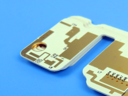
This double-sided RO3010 high-frequency Printed Circuit Board is engineered using Rogers RO3010 ceramic-filled PTFE composite laminate—a material specifically designed for commercial microwave and RF applications requiring high dielectric constant and exceptional electrical stability. With a dielectric constant of 10.2 ± 0.30 at 10 GHz, this RO3010-based board enables significant circuit size reduction while maintaining superior high-frequency performance. The PCB features 0.254mm (0.010") core thickness, 1oz finished copper on both sides, and immersion gold (ENIG) surface finish with black legend and no solder mask ("no silk" top surface). Measuring 65mm x 57mm per piece, this compact double-sided board is ideally suited for size-constrained microwave components including patch antennas, filters, couplers, and impedance-matching networks in telecommunications infrastructure, satellite communications, and automotive radar systems where predictable electrical performance and mechanical stability are critical design requirements.
2. PCB Specifications Overview
Rogers double-sided RO3010 high-frequency PCB is manufactured to precise specifications, ensuring consistent performance for critical RF and microwave applications.
Feature |
Specification |
Technical Note |
Layer Count |
2 Layers (Double-Sided) |
Simple yet effective construction for high-frequency circuits |
Core Material |
Rogers RO3010 |
Ceramic-filled PTFE composite laminate |
Dielectric Constant (Dk) |
10.2 ± 0.30 @10 GHz (process) |
High Dk enables significant circuit miniaturization |
Design Dielectric Constant |
11.20 (8 GHz - 40 GHz) |
For impedance calculations at higher frequencies |
Dissipation Factor (Df) |
0.0022 @10 GHz |
Low loss for efficient high-frequency transmission |
Core Thickness |
0.254 mm (0.010") ± 0.0007" |
Precision thin laminate for controlled impedance |
Copper Weight |
1 oz (35 µm) finished both sides |
Standard weight for conductive traces and ground planes |
Surface Finish |
Immersion Gold (ENIG) |
Excellent solderability and oxidation resistance |
Legend & Solder Mask |
Black Legend, No Solder Mask ("No Silk" on active areas) |
Clean surface for optimal high-frequency performance; black legend for identification |
Board Dimensions |
65 x 57 mm (per piece) |
Compact form factor for space-constrained RF modules |
3. In-Depth: Rogers RO3010Material Technology
Rogers RO3010 is a member of the RO3000® series of high-frequency circuit materials—ceramic-filled PTFE composites intended for use in commercial microwave and RF applications. This family of products was designed to offer exceptional electrical and mechanical stability at competitive prices .
3.1 Key Material Properties
Property |
Value |
Conditions / Test Method |
Dielectric Constant (process) |
10.2 ± 0.30 |
@10 GHz, 23°C, IPC TM-650 2.5.5.5 |
Dielectric Constant (design) |
11.20 |
8 GHz - 40 GHz, Differential Phase Length |
Dissipation Factor |
0.0022 |
@10 GHz, 23°C, IPC TM-650 2.5.5.5 |
Thermal Coefficient of Dk |
-395 ppm/°C |
-50°C to 150°C @10 GHz |
Volume Resistivity |
10⁵ MΩ-cm |
Condition A, IPC TM-650 2.5.17.1 |
Surface Resistivity |
10⁵ MΩ |
Condition A, IPC TM-650 2.5.17.1 |
Decomposition Temperature (Td) |
500 °C |
TGA, ASTM D3850 |
Coefficient of Thermal Expansion (x-axis) |
13 ppm/°C |
-55°C to 288°C, IPC TM-650 2.4.41 |
Coefficient of Thermal Expansion (y-axis) |
11 ppm/°C |
-55°C to 288°C, IPC TM-650 2.4.41 |
Coefficient of Thermal Expansion (z-axis) |
16 ppm/°C |
-55°C to 288°C, IPC TM-650 2.4.41 |
Thermal Conductivity |
0.95 W/m·K |
@50°C, ASTM D5470 |
Copper Peel Strength |
9.4 lbs/in (1 oz ED copper) |
After Solder Float, IPC TM-650 2.4.8 |
Young's Modulus |
1902 MPa (x), 1934 MPa (y) |
@23°C, ASTM D638 |
Dimensional Stability (MD) |
-0.35 mm/m |
Condition A, IPC TM-650 2.2.4 |
Dimensional Stability (CMD) |
-0.31 mm/m |
Condition A, IPC TM-650 2.2.4 |
Flammability |
V-0 |
UL 94 |
Moisture Absorption |
0.05% |
D48/50, IPC TM-650 2.6.2.1 |
Density |
2.8 g/cm³ |
@23°C, ASTM D792 |
Specific Heat Capacity |
0.8 J/g·K |
Calculated |
Lead Free Process Compatible |
Yes |
— |
3.2 Material Advantages
Consistent Mechanical Properties Across Dk Values: RO3000 series laminates exhibit mechanical properties that are consistent regardless of the dielectric constant selected. This allows designers to develop multilayer board designs that use different dielectric constant materials for individual layers without encountering warpage or reliability problems .
Copper-Matched CTE: RO3000 materials exhibit a coefficient of thermal expansion (CTE) in the X and Y axis of 17 ppm/°C (13 ppm/°C for RO3010). This expansion coefficient is matched to that of copper, which allows the material to exhibit excellent dimensional stability, with typical etch shrinkage (after etch and bake) of less than 0.5 mils per inch .
Exceptional PTH Reliability: The Z-axis CTE is 16 ppm/°C, which provides exceptional plated through-hole reliability, even in severe thermal environments .
Stable Electrical Performance: The dielectric constant versus temperature characteristics are well-controlled, ensuring consistent circuit performance across operating temperature ranges .
Standard PTFE Processing: RO3010 laminates can be fabricated into printed circuit boards using standard PTFE circuit board processing techniques, with minor modifications as described in Rogers' application note "Fabrication Guidelines for RO3000 Series High Frequency Circuit Materials" .
4. Applications for RO3010High Dk Material
Rogers RO3010 high-frequency laminate's high dielectric constant (10.2) enables significant wavelength reduction, making it ideal for size-constrained microwave components :
Patch Antennas: Miniaturized antenna elements for GPS, satellite communications, and wireless infrastructure
Filters and Couplers: Compact bandpass filters, directional couplers, and power dividers where size reduction is critical
Impedance Matching Networks: Broadband matching circuits for amplifiers and mixers
Microwave Transceivers: Compact transceiver modules for point-to-point radio links
Automotive Radar: 24 GHz and 77 GHz radar system components
Satellite Communications: LNB and feed network components requiring precise phase matching
Test Equipment: High-frequency test fixtures and impedance standard substrates
5. Design and Fabrication Considerations
5.1 Impedance Control
With design Dk of 11.20 for higher frequency calculations, careful impedance modeling is required for 50-ohm transmission lines. For microstrip structures on 0.254mm RO3010 with 1oz copper, typical 50-ohm line widths are significantly narrower than on lower Dk materials, enabling compact circuit layouts .
5.2 Processing Guidelines
Rogers RO3010 requires standard PTFE circuit board processing techniques as detailed in Rogers' fabrication guidelines. Key considerations include:
Plasma treatment or sodium etching may be required for through-hole plating
Careful handling to prevent contamination of PTFE surfaces
Appropriate drilling parameters for ceramic-filled PTFE composites
Compatibility with immersion gold (ENIG) finish as specified
5.3 Thermal Management
With thermal conductivity of 0.95 W/m·K, RO3010 offers improved heat dissipation compared to standard PTFE materials. For power applications, thermal via arrays and ground plane optimization are recommended .
6. Conclusion
This double-sided high-frequency PCB, constructed with Rogers RO3010 ceramic-filled PTFE laminate, delivers exceptional electrical and mechanical stability for demanding microwave and RF applications. RO3010 material's high dielectric constant (10.2 ± 0.30) enables significant circuit size reduction while maintaining low loss (0.0022 dissipation factor) and excellent thermal performance. With CTE matched to copper (13/11 ppm/°C X/Y) and exceptional plated through-hole reliability (16 ppm/°C Z-axis), this board ensures consistent performance across temperature extremes and severe thermal environments. The compact 65mm x 57mm format with immersion gold finish, black legend, and 1oz copper cladding makes RO3010 PCB ideally suited for telecommunications infrastructure, satellite communications, automotive radar, and test equipment applications where predictable electrical behavior, mechanical stability, and space efficiency are equally critical.
Founded in 2003, Shenzhen Bicheng Electronics Technology Co., Ltd is an established high frequency PCB supplier and exporter in Shenzhen, China, serving customers worldwide.
We are devoted to delivering high-frequency PCB products and solutions of the highest quality, along with customized service. Get in touch with us to start your project !
Visit https://www.bicheng-enterprise.com to learn more.