

 Home
-
Newly shipped PCBs
-
8-Layer Rogers RO4003C RF and Microwave PCB with Optimized Fabrication Guidelines for Complex Multilayer Designs
Home
-
Newly shipped PCBs
-
8-Layer Rogers RO4003C RF and Microwave PCB with Optimized Fabrication Guidelines for Complex Multilayer Designs
8-Layer Rogers RO4003C RF and Microwave PCB with Optimized Fabrication Guidelines for Complex Multilayer Designs
Printed Circuit Boards are custom-made products; the images and specifications provided are for reference only.
1. Introduction: Thick Multilayer PCB with Rogers RO4003C Cores
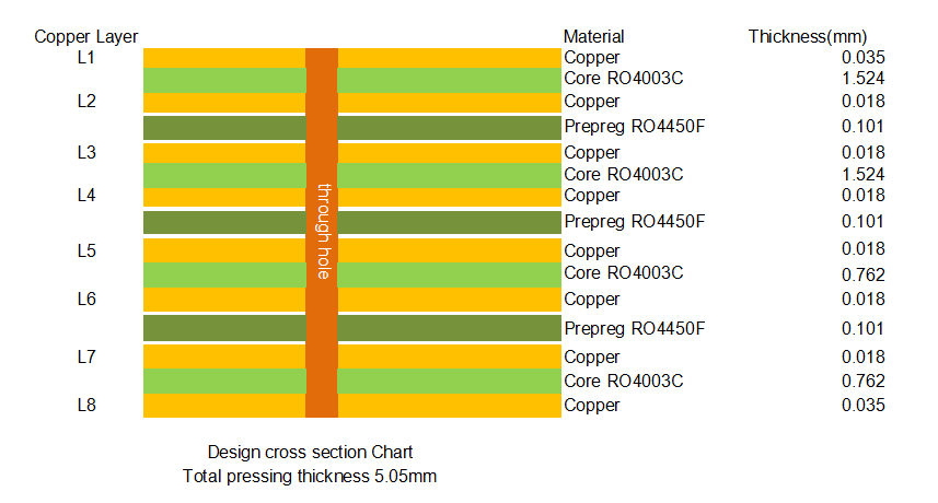
This advanced 8-layer high-frequency Printed Circuit Board is precision-engineered using four Rogers RO4003C cores in a stacked configuration—comprising 1.524mm, 1.524mm, 0.762mm, and 0.762mm thicknesses—bonded with RO4450F prepreg material. Designed for demanding RF and microwave applications requiring thick board construction (5.05mm finished thickness) and exceptional thermal-mechanical stability, RO4003C multi-layer PCB represents a sophisticated multilayer solution where precise impedance control and signal integrity are paramount. The board features 1oz finished copper on outer layers and 0.5oz on inner layers, with immersion gold (ENIG) surface finish, green solder mask with white legend on the bottom side only, and a clean top surface optimized for component mounting. Measuring 91mm x 77mm per piece, this 8-layer construction is ideal for high-power RF amplifiers, aerospace communication systems, and industrial radar applications where board rigidity, thermal dissipation, and consistent electrical performance across thick laminates are critical requirements.
2. PCB Specifications Overview
Rogers 8-layer RO4003C high-frequency PCB is manufactured to precise specifications, ensuring consistent performance for critical RF and microwave applications.
Feature |
Specification |
Technical Note |
Layer Count |
8 Layers |
Four-core construction for complex routing and power distribution |
Core Material |
Rogers RO4003C (four cores) |
1.524mm + 1.524mm + 0.762mm + 0.762mm stacking |
Prepreg Material |
Rogers RO4450F |
Compatible bonding material for multilayer construction |
Total Thickness |
5.05 mm (finished) |
Thick board construction for high mechanical stability |
Copper Weight (Outer) |
1 oz (35 µm) finished |
Optimized for outer layer signal transmission and component attachment |
Copper Weight (Inner) |
0.5 oz (17.5 µm) finished |
Balanced for inner layer routing and power plane requirements |
Surface Finish |
Immersion Gold (ENIG) |
Excellent solderability, wire-bondability, and oxidation resistance |
Solder Mask & Legend |
Top: Green Mask, No Legend; Bottom: Green Mask, White Legend |
Clean top surface for RF components; bottom side for identification |
Board Dimensions |
91 x 77 mm (per piece) |
Compact footprint for integrated system assemblies |
3. Rogers RO4000 Series Multilayer Fabrication Guidelines
The successful fabrication of thick multilayer boards using RO4003C high-frequency substrate requires adherence to established processing guidelines developed by Rogers Corporation for their hydrocarbon ceramic laminate systems . These guidelines ensure optimal inner-layer preparation, drilling quality, and final circuit integrity for complex stack-ups.
3.1 Material Storage and Handling
Fully clad RO4003C laminates should be stored at room temperature between 50-90°F (10-32°C) to maintain material stability . A first-in-first-out inventory system is recommended, along with a method to track material lot numbers through PCB processing and delivery of finished circuits. This traceability is particularly important for thick multilayer constructions where material consistency across multiple cores directly impacts final board performance .
3.2 Inner Layer Preparation
Tooling Considerations: RO4003C laminates are compatible with many pinned and pinless tooling systems . The choice between round or slotted pins, external or internal pinning, standard or multi-line tooling, and pre versus post-etch punching depends on fabrication facility capabilities and final registration requirements. For thick multilayer boards with four cores, slotted pins, a multi-line tooling format, and post-etch punching typically meet most registration needs .
Surface Preparation for Photoresist Processing: Depending upon RO4003C core thickness, copper surfaces can be prepared for photo imaging using chemical or mechanical processes . Thinner cores (such as the 0.762mm layers) should be prepared using a chemical process consisting of cleaning, micro-etching, water rinsing, and drying steps. Thicker cores (1.524mm) are compatible with mechanical scrub systems . RO4003C materials work with most liquid and dry film photo-resists and, once patterned, can be processed through develop, etch, and strip (DES) systems typically used for FR-4 materials .
Oxide Treatment: RO4003C cores can be processed through any copper oxide or oxide alternative process in preparation for multi-layer bonding . The best treatment choice is typically the one recommended in the guidelines supporting the chosen prepreg system—in this case, RO4450F .
Multi-Layer Bonding: RO4003C laminates are compatible with many thermosetting adhesive systems . For thick 8-layer constructions with four cores, bond cycle parameters should follow the guidelines for the selected prepreg material, with careful attention to temperature ramp rates and pressure profiles to ensure complete resin flow and void-free bonding across the 5.05mm stack .
3.3 Drilling Guidelines for RO4003C Multilayer Boards
Drilling Considerations: Standard entry materials (aluminum or thin pressed phenolic) and exit materials (pressed phenolic or fiber board) can be used when drilling RO4003C bonded assemblies in one-up or multi-up stacks . For thick 5.05mm boards, stack height must be carefully managed to ensure drill breakthrough and debris evacuation.
RO4003C materials are compatible with a broad range of drilling parameters . However, drilling speeds greater than 500 surface feet per minute (SFM) should be avoided . Chip loads greater than 0.002"/rev are recommended for mid-range and large diameter tools, while lower chip loads (<0.002"/rev) are recommended for small (<0.0135") diameter drills .
Tool Selection and Life: Standard geometry carbide drills are preferred over undercut styles as they more effectively evacuate debris from holes during drilling . Hit counts should be based on inspection of plated-through holes (PTH's) and not the appearance of the tools. Drilling RO4003C laminates results in accelerated drill wear, but hole wall quality is determined by the size distribution of the ceramic powder, not by the cutting edge condition. A hole wall roughness ranging from 8 to 25 µm is expected and remains consistent from initial hit through several thousand hits .
Recommended Drilling Parameters for RO4003C:
Parameter |
Recommended Range |
Surface Speed |
300-500 SFM (90 to 150 m/min) |
Chip Load |
0.002"-0.004"/rev (0.05-0.10 mm/rev) |
Retract Rate |
500 IPM (12.7 m/min) for tools <0.0135"; 1000 IPM for all others |
Tool Type |
Standard carbide |
Tool Life |
2,000-3,000 hits |
3.4 PTH Processing for Thick Multilayer Boards
Surface Preparation: Thick multi-layer constructions (5.05mm) can be processed through conveyorized deburring equipment using oscillating nylon brushes to abrade copper surfaces . The thickness of the material and registration requirements should guide the choice of deburring and surface preparation method.
Desmear Considerations: Desmear is typically not required for drilled holes in double-sided boards due to the high glass transition temperature of RO4003C (>280°C), which minimizes smear occurrence . However, multi-layer boards with RO4450F prepreg may require desmear depending on bondply requirements. If needed, a single or double pass through alkaline permanganate or a CF4/O2 plasma process may be used .
Important: Etchback of RO4003C laminate layers should be avoided as this might result in aggressive removal of resin near copper layers and loosening of filler particles on the hole wall .
Metal Deposition: RO4003C materials do not require special treatments prior to metallization and are compatible with electroless copper processing and direct deposition of ionic and colloidal conductive layers . A copper flash plate (0.00025") prior to imaging may be considered for boards with high aspect ratio holes—particularly relevant for 5.05mm thick constructions .
3.5 Copper Plating and Outer Layer Processing
RO4003C laminates are compatible with panel and pattern processing using standard acid copper and electrolytic tin or tin/lead plating . Once plated, they can be processed through any standard strip/etch/strip (SES) process. The post-etch surface should be preserved as it bonds very well with direct screened and photo-imageable solder masks .
Final Metal Finishes: RO4003C laminates are compatible with organic solderability preservatives (OSP's), hot air solder leveling (HASL), and most chemically deposited or electroplated finishes including immersion gold (ENIG) as specified for this design .
3.6 Final Circuitization and Routing
Circuits made using RO4003C laminates can be individualized by dicing, sawing, shearing, routing, or punching . V-scoring and breakaway tabs can facilitate individualization after automated assembly.
Routing Recommendations:
Parameter Recommendation
Parameter |
Recommendation |
Tool Type |
Carbide multi-fluted spiral chip breakers or diamond cut router bits |
Surface Speed |
Below 500 SFM to maximize tool life |
Chip Load |
0.0010-0.0015" (0.0254-0.0381mm)/rev |
Stack Height |
Maximum based on 70% of flute length minus backer penetration |
3.7 Shelf Life and Long-Term Storage
Rogers high-frequency laminates can be stored for extended durations under ambient room temperatures (55-85°F, 13-30°C) and humidity levels . At room temperature, the dielectric materials are inert to high humidity. However, metal claddings such as copper can oxidize during exposure to high humidity (oxidation is easily removed in a standard micro-etch process). Over extended periods (>5 years), exposed dielectric along panel edges may experience detectable oxidation, but standard tooling hole and trim loss typically removes affected areas .
Important Note: Prolonged exposure in oxidative environments may cause changes to dielectric properties of hydrocarbon-based materials. The rate of change increases at higher temperatures and depends on circuit design. While Rogers materials have been used successfully in innumerable applications with rare oxidation-related performance problems, evaluation of each material and design combination for fitness over the entire product life is recommended .
4. Material Advantages of RO4003C for Thick Multilayer Designs
Rogers RO4003C laminate offers distinct advantages for complex 8-layer constructions requiring thick board build-ups :
Property |
Value |
Benefit for 8-Layer Design |
Dielectric Constant (Dk) |
3.38 ± 0.05 @10 GHz |
Consistent impedance across all eight layers |
Dissipation Factor (Df) |
0.0027 @10 GHz |
Minimal signal loss in RF paths |
Thermal Coefficient of Dk |
+40 ppm/°C |
Stable performance across operating temperatures |
CTE (Z-axis) |
46 ppm/°C |
Reliable PTH integrity in thick 5.05mm board |
Water Absorption |
0.04% |
Maintains electrical properties in humid environments |
Tg (Glass Transition) |
>280°C |
Supports lead-free assembly and high-temperature operation |
Thermal Conductivity |
0.71 W/m/°K |
Effective heat dissipation for power applications |
5. Target Applications for 8-Layer RO4003C PCBs
This 8-layer, 5.05mm thick construction with RO4003C cores is ideally suited for demanding applications requiring mechanical rigidity, thermal management, and high-frequency performance :
High-Power RF Amplifiers: Base station power amplifiers requiring thick copper and robust thermal management
Aerrowave & Defense Systems: Radar transmitters, electronic warfare modules, and satellite communication equipment
Industrial Radar: Level sensing radar systems operating in harsh industrial environments
Medical Imaging: MRI and RF ablation equipment requiring stable dielectric properties
Test & Measurement: High-frequency test fixtures and burn-in boards requiring dimensional stability
Automotive Radar: Long-range 77GHz radar modules requiring precise layer-to-layer registration
6. Conclusion
This 8-layer high-frequency PCB, constructed with four Rogers RO4003C cores and RO4450F prepreg, represents a sophisticated multilayer solution for applications requiring thick board construction (5.05mm) without compromising high-frequency performance. The material's tightly controlled dielectric constant (3.38 ± 0.05) and low dissipation factor (0.0027) ensure minimal signal loss through millimeter-wave frequencies, while its FR-4 compatible processing eliminates the cost premiums associated with traditional microwave laminates. The implementation of four-core stacking with precise fabrication following Rogers' established guidelines—from inner-layer preparation and drilling to PTH processing and final routing—ensures reliable performance in demanding environments.
Founded in 2003, Shenzhen Bicheng Electronics Technology Co., Ltd is an established high frequency PCB supplier and exporter in Shenzhen, China, serving customers worldwide.
We are devoted to delivering high-frequency PCB products and solutions of the highest quality, along with customized service. Get in touch with us to start your project !
Visit https://www.bicheng-enterprise.com to learn more.
Rogers 6-Layer High-Frequency PCB with 0.203mm Rogers RO4003C laminate and Advanced Back Drilling Technology for 5G, Automotive Radar and Aerospace Applications
Double-Sided Rogers RO3010 High-Frequency PCB with 10mil RO3010 Ceramic-Filled PTFE Laminate for Commercial Microwave and RF Applications