

 Home
-
Newly shipped PCBs
-
TFA615 2-Layer 0.508mm PTFE-Ceramic PCB Aerospace-Grade PCB Board for Radar and Satellite Communications
Home
-
Newly shipped PCBs
-
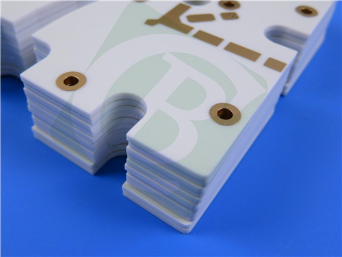
TFA615 2-Layer 0.508mm PTFE-Ceramic PCB Aerospace-Grade PCB Board for Radar and Satellite Communications
TFA615 2-Layer 0.508mm PTFE-Ceramic PCB Aerospace-Grade PCB Board for Radar and Satellite Communications
Printed Circuit Boards are custom-made products; the images and specifications provided are for reference only.
1. TFA615 PCB Material Properties
TFA615 PCB utilizes an advanced polytetrafluoroethylene (PTFE) ceramic composite dielectric substrate, manufactured through an innovative process that differs from traditional glass fiber cloth impregnation. By blending PTFE resin with specialized ceramics and employing a unique lamination technique, this aerospace-grade high-frequency material delivers outstanding electrical, thermal, and mechanical performance. With no glass fiber cloth in its construction, the substrate eliminates fiberglass-induced effects during electromagnetic wave propagation, ensuring excellent frequency stability, minimal dielectric loss, and reduced X/Y/Z anisotropy. Its low thermal expansion coefficient closely matches that of copper foil, providing exceptional dimensional and dielectric temperature stability ideal for high-reliability aerospace and radar applications.
2. PCB Construction & Specifications
Board Type: 2-Layer Rigid PCB
Base Material: TFA615 PTFE-Ceramic Composite Laminate
Quality Standard: IPC-Class-2
Board Dimensions: 206mm x 54mm (±0.15mm)
Finished Thickness: 0.6mm
Copper Weight: 1oz (35μm) outer layers
Minimum Trace/Space: 4/6 mils
Minimum Hole Size: 0.3mm
Blind Vias: Not Applicable
Via Plating Thickness: 20μm
Surface Finish: Immersion Gold
Solder Mask: None (Top & Bottom)
Silkscreen: None (Top & Bottom)
Electrical Test: 100% tested prior to shipment
3. PCB Stackup Configuration
Layer 1: Copper – 35μm
Core: TFA615 Laminate – 0.508mm (20mil)
Layer 2: Copper – 35μm
4. PCB Statistics
Components: 35
Total Pads: 153
Thru Hole Pads: 121
Top SMT Pads: 32
Bottom SMT Pads: 0
Vias: 77
Nets: 2
5. Artwork & Standards
Type of artwork supplied: Gerber RS-274-X
Quality standard: IPC-Class-2
Availability: worldwide
6. Material Features
Dielectric Constant: 6.15 ± 0.12 @ 10GHz
Dissipation Factor: 0.0015 @ 10GHz, 0.0017 @ 20GHz
CTE Values: X-axis 16 ppm/°C, Y-axis 16 ppm/°C, Z-axis 29 ppm/°C (–55°C to 288°C)
Thermal Conductivity: 0.8 W/mk
Moisture Absorption: 0.06%
Flammability Rating: UL 94-V0
Decomposition Temperature: 503°C
7. Performance Benefits
Excellent frequency stability and signal integrity
Minimized dielectric loss and anisotropy
Copper-matched CTE for reliable plated through-holes
Suitable for high-frequency and high-speed designs
Aerospace-grade reliability under extreme conditions
Consistent performance across temperature ranges
8. Target Applications
Aerospace and in-cabin avionics equipment
Microwave systems and antennas
Early warning and airborne radar systems
Phased array antennas and beamforming networks
Satellite communication and navigation systems
High-frequency power amplifiers
9. Global Availability
This TFA615-based PCB is available for global manufacturing and delivery, supporting prototyping and volume production for international aerospace, defense, and telecommunications sectors.
10. Quality Assurance
100% electrical testing before shipment
Compliance with IPC-Class-2 standards
Validation of high-frequency performance
Thermal and environmental reliability testing
Mechanical stability and durability certification