

 Home
-
Newly shipped PCBs
-
Rogers RO4003C Multilayer PCB 4-Layer 4.8mm Thick Rogers 4003C High Frequency Printed Circuit Board
Home
-
Newly shipped PCBs
-
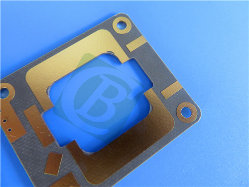
Rogers RO4003C Multilayer PCB 4-Layer 4.8mm Thick Rogers 4003C High Frequency Printed Circuit Board
Rogers RT duroid 6202 2-Layer 0.2mm PCB Low-Loss High-Frequency Board for Phased Array Antennas
Printed Circuit Boards are custom-made products; the images and specifications provided are for reference only.
1. Rogers RT/duroid 6202 PCB Material Properties
Rogers RT duroid 6202 PCB utilizes advanced low-loss, low-dielectric-constant laminates with limited woven glass reinforcement, providing the essential electrical and mechanical properties required for designing complex microwave structures. These high-frequency circuit materials deliver both mechanical reliability and electrical stability, with exceptional dimensional stability ranging from 0.05 to 0.07 mils/inch achieved through optimized woven glass reinforcement. This superior dimensional control frequently eliminates the need for double etching processes to maintain tight positional tolerances, streamlining manufacturing while ensuring precision performance in demanding microwave applications.
2. PCB Construction & Specifications
Board Type: 2-Layer Rigid PCB
Base Material: Rogers RT duroid 6202 High-Frequency Laminate
Quality Standard: IPC-Class-2
Board Dimensions: 37mm x 29mm
Finished Thickness: 0.2mm
Copper Weight: 1oz (35μm) outer layers
Minimum Trace/Space: 5/6 mils
Minimum Hole Size: 0.2mm
Blind Vias: Not Applicable
Via Plating Thickness: 20μm
Surface Finish: Immersion Gold
Solder Mask: None (Top & Bottom)
Silkscreen: None (Top & Bottom)
Electrical Test: 100% tested prior to shipment
3. PCB Stackup Configuration
Layer 1: Copper - 35μm
Substrate: Rogers RT duroid 6202 - 0.127mm (5mil)
Layer 2: Copper - 35μm
4. PCB Statistics
Components: 3
Total Pads: 16
Thru Hole Pads: 10
Top SMT Pads: 6
Bottom SMT Pads: 0
Vias: 8
Nets: 2
5. Artwork & Standards
Type of artwork supplied: Gerber RS-274-X
Accepted standard: IPC-Class-2
Availability: worldwide
6. Material Features
Dielectric Constant: 2.94±0.04 to 3.06±0.04 (thickness dependent) @ 10GHz/23°C
Dissipation Factor: 0.0015 @ 10GHz/23°C
Thermal Coefficient of Dk: 5 ppm/°C @ 10GHz (-50 to +150°C)
CTE Values: X-axis 15 ppm/°C, Y-axis 15 ppm/°C, Z-axis 30 ppm/°C (-55 to 288°C)
Decomposition Temperature: 500°C (TGA)
Thermal Conductivity: 0.68 W/m/K
Moisture Absorption: 0.04%
Flammability Rating: UL 94-V0
7. Performance Benefits
Low loss for excellent high-frequency performance
In-plane expansion coefficient matched to copper
Excellent electrical and mechanical properties
Very low etch shrinkage for precision circuits
Superior dimensional stability
Streamlined manufacturing process
Enhanced reliability in microwave applications
8. Target Applications
Phased Array Antennas
Ground Based and Airborne Radar Systems
Global Positioning System Antennas
Power Backplanes
Commercial Airline Collision Avoidance Systems
Military Radar Equipment
Aerospace Communication Systems
9. Global Availability
This Rogers RT duroid 6202 based PCB solution is available for worldwide manufacturing and distribution, supporting both prototype development and volume production requirements across global aerospace and defense markets.
10. Quality Assurance
100% electrical testing prior to shipment
IPC-Class-2 quality standards compliance
High-frequency performance validation
Dimensional stability verification
Mechanical reliability testing
Environmental resistance certification
Consistent microwave performance monitoring