

 Home
-
Newly shipped PCBs
-
Rogers RO4725JXR 2-Layer 30.7mil PCB Antenna-Grade Low-PIM Circuit Board for Cellular Base Stations
Home
-
Newly shipped PCBs
-
Rogers RO4725JXR 2-Layer 30.7mil PCB Antenna-Grade Low-PIM Circuit Board for Cellular Base Stations
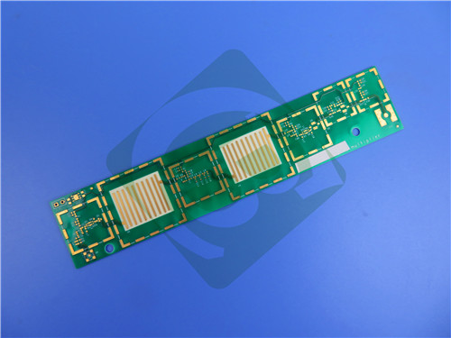
Rogers RO4725JXR 2-Layer 30.7mil PCB Antenna-Grade Low-PIM Circuit Board for Cellular Base Stations
Printed Circuit Boards are custom-made products; the images and specifications provided are for reference only.
1. Rogers RO4725JXR PCB Material Properties
Rogers RO4725JXR PCB utilizes advanced hydrocarbon/ceramic/woven glass antenna-grade laminates that provide a reliable and cost-effective alternative to conventional PTFE-based materials. These specialized dielectric materials feature resin systems engineered to deliver optimal antenna performance characteristics while maintaining full compatibility with standard FR-4 manufacturing processes and high-temperature lead-free soldering. Unlike traditional PTFE-based laminates, RO4725JXR PCBs eliminate the need for specialized plated through-hole preparation treatments, offering designers an affordable solution that balances both cost efficiency and high-frequency performance.
RO4725JXR PCBs possess the precise mechanical and electrical properties essential for modern antenna design, featuring a dielectric constant (Dk) of 2.55 and loss tangent (Df) of 0.0022 measured at 2.5 GHz when using LoPro Reverse Treated EDC Foil. These electrical characteristics enable antenna designers to achieve substantial gain values while minimizing signal loss. The materials demonstrate exceptional passive intermodulation (PIM) performance with values better than -160 dBc (43dBm 1,900MHz signal), making them particularly suitable for high-performance cellular applications where signal purity is critical.
2. PCB Construction & Specifications
Board Type: 2-Layer Rigid PCB
Base Material: Rogers RO4725JXR Antenna-Grade Laminate
Quality Standard: IPC-Class-2
Board Dimensions: 53mm x 79mm (±0.15mm)
Finished Thickness: 0.8mm
Copper Weight: 1oz (35μm) outer layers
Minimum Trace/Space: 4/7 mils
Minimum Hole Size: 0.3mm
Blind Vias: Not Applicable
Via Plating Thickness: 20μm
Surface Finish: Immersion Gold
Solder Mask: None (Top & Bottom)
Silkscreen: None (Top & Bottom)
Electrical Test: 100% tested prior to shipment
3. PCB Stackup Configuration
Layer 1: Copper - 35μm
Core: Rogers RO4725JXR Laminate - 0.78mm (30.7mil)
Layer 2: Copper - 35μm
4. PCB Statistics
Components: 6
Total Pads: 39
Thru Hole Pads: 31
Top SMT Pads: 8
Bottom SMT Pads: 0
Vias: 20
Nets: 2
5. Artwork & Standards
Type of artwork supplied: Gerber RS-274-X
Quality standard: IPC-Class-2
Availability: worldwide
6. Material Features
Dielectric Constant: 2.55 ± 0.05 @ 10GHz/23°C
Dissipation Factor: 0.0026 @ 10GHz/23°C, 0.0022 @ 2.5GHz
Thermal Coefficient of Dielectric Constant: +34 ppm/°C
CTE Values: X-axis 13.9 ppm/°C, Y-axis 19 ppm/°C, Z-axis 25.6 ppm/°C
Glass Transition Temperature: >280°C
PIM Performance: -166 dBc
7. Performance Benefits
Low loss dielectric with low profile foil
Minimized insertion loss for improved signal transmission
Dielectric constant matched to standard PTFE-based antenna materials
Reduced passive intermodulation (PIM) for cleaner signals
Consistent circuit performance across temperature variations
Cost-effective alternative to traditional PTFE laminates
FR-4 process compatibility for simplified manufacturing
8. Target Applications
Cellular Base Station Antennas
Wireless Communication Systems
Mobile Network Infrastructure
5G Antenna Arrays
RF Antenna Systems
Telecommunications Equipment
Network Base Station Components
9. Global Availability
Rogers RO4725JXR PCB solution is available for worldwide manufacturing and distribution, supporting both prototype development and volume production requirements across global telecommunications markets.
10. Quality Assurance
100% electrical testing prior to shipment
IPC-Class-2 quality standards compliance
High-frequency performance validation
PIM performance testing and verification
Thermal stability assessment
Mechanical reliability certification
Consistent dielectric performance monitoring