

 Home
-
Newly shipped PCBs
-
F4BTME320 2-Layer 60mil PTFE PCB Low-PIM High-Frequency Board for Aerospace and Radar Systems
Home
-
Newly shipped PCBs
-
F4BTME320 2-Layer 60mil PTFE PCB Low-PIM High-Frequency Board for Aerospace and Radar Systems
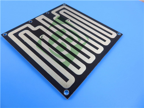
F4BTME320 2-Layer 60mil PTFE PCB Low-PIM High-Frequency Board for Aerospace and Radar Systems
Printed Circuit Boards are custom-made products; the images and specifications provided are for reference only.
1. F4BTME Series Nano-Ceramic PTFE Laminates
F4BTME series laminate achieves a unique synergy of critical performance properties through its advanced nano-ceramic and PTFE composite structure. This platform delivers not only an enhanced dielectric constant and superior thermal stability but also exceptional electrical characteristics—all while maintaining the proven reliability of the F4BM dielectric foundation.
This innovative material system provides outstanding heat resistance, reduced thermal expansion coefficient, increased insulation resistance, and improved thermal conductivity while maintaining ultralow loss properties.
F4BTME PCBs are specifically optimized with reverse-treated RTF copper foil, delivering exceptional performance in passive intermodulation (PIM), precise impedance control, and minimized conductor loss - making them ideal for demanding high-frequency applications where signal integrity is critical.
2. PCB Construction & Specifications
Board Type: 2-Layer Rigid PCB
Base Material: F4BTME320 High-Frequency Laminate
Quality Standard: IPC-6012 Class 2
Board Dimensions: 136mm x 98mm (±0.15mm)
Finished Thickness: 1.6mm
Copper Weight: 1oz (35μm) outer layers
Minimum Trace/Space: 5/5 mils
Minimum Hole Size: 0.4mm
Blind Vias: Not Applicable
Via Plating Thickness: 20μm
Surface Finish: Immersion Tin
Solder Mask: Black (Top), None (Bottom)
Silkscreen: None (Top & Bottom)
Electrical Test: 100% tested prior to shipment
3. PCB Stackup Configuration
Layer 1: Copper - 35μm
Core: F4BTME320 Laminate - 1.524mm (60mil)
Layer 2: Copper - 35μm
4. Design Statistics
Component Count: 31
Total Pads: 105
Thru-Hole Pads: 71
SMT Pads (Top): 34
SMT Pads (Bottom): 0
Vias: 28
Nets: 2
Artwork Format: Gerber RS-274-X
5. Material Characteristics (F4BTME320)
Dielectric Constant: 3.2 ± 0.06 @ 10GHz
Dissipation Factor: 0.002 @ 10GHz, 0.0026 @ 20GHz
CTE Values: X-axis 13 ppm/°C, Y-axis 15 ppm/°C, Z-axis 58 ppm/°C (-55°C to 288°C)
Thermal Coefficient of Dk: -75 ppm/°C (-55°C to 150°C)
PIM Performance: < -160 dBc
Moisture Absorption: 0.05%
6. Performance Advantages
Ultra-Low Passive Intermodulation (PIM) for Critical Communications
Exceptional Thermal Stability Across Wide Temperature Ranges
Precise Impedance Control with Tight Dk Tolerance
Minimized Signal Loss at High Frequencies
Superior Thermal Management Capabilities
Excellent Moisture Resistance for Harsh Environments
Optimized for High-Frequency, Phase-Sensitive Applications
7. Target Applications
Aerospace Avionics and Cabin Equipment Systems
Military and Civilian Radar Systems
Phased Array and Phase-Sensitive Antennas
Satellite Communication Equipment
Microwave and RF Feed Networks
Defense Electronic Systems
High-Reliability Communication Infrastructure
8. Global Availability
This F4BTME320 PCB solution is available for worldwide manufacturing and distribution, supporting both prototype development and volume production requirements across global markets.