

 Home
-
Newly shipped PCBs
-
F4BM220 High-Frequency PCB 2-Layer 6.0mm PTFE Board with Enhanced Dimensional Stability
Home
-
Newly shipped PCBs
-
F4BM220 High-Frequency PCB 2-Layer 6.0mm PTFE Board with Enhanced Dimensional Stability
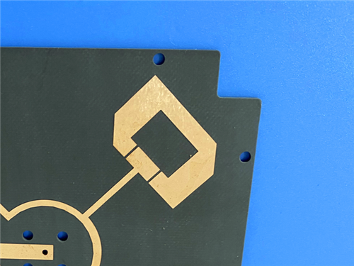
F4BM220 High-Frequency PCB 2-Layer 6.0mm PTFE Board with Enhanced Dimensional Stability
Printed Circuit Boards are custom-made products; the images and specifications provided are for reference only.
1. Introduction of F4BM220 PCB
Wangling's F4BM220 high-frequency laminates are manufactured through scientific formulation and precision pressing technology, combining fiberglass cloth, polytetrafluoroethylene (PTFE) resin, and PTFE film. Compared to the F4B220 series, the F4BM220 exhibits enhanced electrical performance, characterized by reduced dielectric loss, higher insulation resistance, and improved operational stability. It serves as a reliable domestic substitute for comparable imported materials.
The F4BM220 and F4BME220 PCBs share an identical dielectric layer composition but differ in copper foil configuration: the F4BM220 uses ED copper foil and is suitable for applications without passive intermodulation (PIM) requirements, while the F4BME220 employs reverse-treated foil (RTF), delivering superior PIM performance, finer line control, and reduced conductor loss.
By carefully adjusting the PTFE-to-fiberglass cloth ratio, both the F4BM220 PCB and F4BME220 PCB enable precise control over the dielectric constant while maintaining low signal loss and strengthened dimensional stability. A higher dielectric constant corresponds to an increased proportion of fiberglass, which enhances dimensional stability, lowers the coefficient of thermal expansion, improves temperature drift performance, and leads to a marginal increase in dielectric loss.
2. Features (F4BM220 PCB)
- Dielectric constant (Dk) of 2.2±0.04 at 10GHz
- Dissipation factor of .001 at 10GHz
- CTE x-axis of 25 ppm/°C, CTE y-axis of 34 ppm/°C, CTE z-axis of 240 ppm/°C, -55°C to 288°C
- Thermal coefficient of Dk at-142 ppm/°C, -55°C to 150°C
- Moisture absorption of ≤0.08%
- Flammability of UL-94 V0
3. PCB Construction details:
- Base material: F4BM220
- Layer count: double sided
- Board dimensions: 90mm x 90 mm=1PCS, +/- 0.15mm
- Minimum Trace/Space: 10/10 mils
- Minimum Hole Size: 0.7mm
- No Blind vias.
- Finished board thickness: 6.1mm
- Finished Cu weight: 1oz (1.4 mils) outer layers
- Via plating thickness: 20 μm
- Surface finish: Immersion Gold
- Top Silkscreen: NO
- Bottom Silkscreen: No
- Top Solder Mask: No
- Bottom Solder Mask: No
- 100% Electrical test used prior to shipment
4. PCB Stackup: 2-layer rigid PCB
Copper_layer_1 - 35 μm
F4BM220 Core - 6.0 mm
Copper_layer_2 - 35 μm
5. PCB Statistics:
Components: 2
Total Pads: 9
Thru Hole Pads: 5
Top SMT Pads: 4
Bottom SMT Pads: 0
Vias: 4
Nets: 2
6. Type of artwork supplied: Gerber RS-274-X
7. Quality standard: IPC-Class-2
8. Availability: worldwide
9. Some Typical Applications:
- Microwave, RF, and radar systems
- Phase shifters
- Power dividers, couplers, combiners
- Feed networks
- Phase-sensitive antennas, phased array antennas
- Satellite communications
- Base station antennas