

 Home
-
Newly shipped PCBs
-
Double Sided TP600 PCB 5.08mm Thick High Frequency PCB for Satellite Navigation and Miniaturized Antennas
Home
-
Newly shipped PCBs
-
Double Sided TP600 PCB 5.08mm Thick High Frequency PCB for Satellite Navigation and Miniaturized Antennas
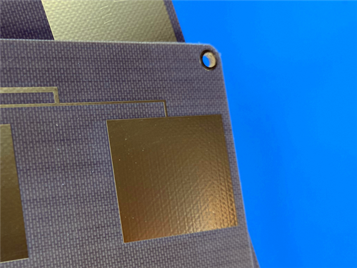
Double Sided TP600 PCB 5.08mm Thick High Frequency PCB for Satellite Navigation and Miniaturized Antennas
Printed Circuit Boards are custom-made products; the images and specifications provided are for reference only.
1. TP600 PCB Introduction
TP600 PCB utilizes a unique high-frequency thermoplastic material featuring a ceramic and polyphenylene oxide (PPO) resin dielectric layer without fiberglass reinforcement. This innovative construction allows precise adjustment of dielectric properties through ceramic-to-resin ratio control, delivering excellent dielectric performance and high reliability. As part of the TP series, TP600 laminate represents the double-sided copper clad variant (TP-2), manufactured through specialized processes to ensure consistent electrical characteristics and optimal performance in demanding high-frequency applications.
2. PCB Construction Details
Specification Category |
Details |
Base Material |
TP600 |
Layer Count |
Double Sided |
Board Dimensions |
25mm x 25mm (±0.15mm) |
Finished Thickness |
5.1mm |
Copper Weight |
1 oz Outer Layers |
Min. Trace/Space |
6/7 mils |
Min. Hole Size |
0.7mm |
Blind Vias |
None |
Surface Finish |
ENIG |
Solder Mask |
None |
Silkscreen |
None |
Electrical Test |
100% |
3. Stackup Structure
This double-sided TP600 PCB configuration employs a substantial TP600 core with 5.08mm (200mil) thickness, positioned between two 35μm copper layers to create a robust 5.1mm profile suitable for high-power and precision RF applications.
4. Board Statistics
Components: 4
Total Pads: 16 (10 Thru-Hole, 6 Top SMT)
Vias: 9
Nets: 2
Files: Gerber RS-274-X
Standard: IPC-Class-2
Availability: Worldwide
5. TP600 Material Features
Dielectric Constant: 6.0±0.12 @ 10GHz
Dissipation Factor: 0.0010 @ 10GHz
Thermal Coefficient of Dk: -50 ppm/°C
CTE: X 50/Y 50/Z 60 ppm/°C
Thermal Conductivity: 0.55 W/mK
Moisture Absorption: 0.01%
Flammability: UL 94-V0
6. Key Benefits
Customizable dielectric constant from 3 to 25
Stable electrical performance across frequencies
Low dielectric loss with minimal frequency variation
No fiberglass reinforcement for uniform properties
Excellent reliability in harsh environments
Suitable for precision high-frequency circuits
7. Typical Applications
Global Satellite Navigation Systems
Missile-borne Electronic Systems
Fuze Technology Applications
Miniaturized Antenna Designs
Aerospace Communication Systems
High-Reliability Military Electronics