

 Home
-
Newly shipped PCBs
-
4-layer 0.833mm Rogers RT/duroid 5880 PCB and TG170 FR-4 : Advanced Multi-Layer RF Solution with Green Solder Mask
Home
-
Newly shipped PCBs
-
4-layer 0.833mm Rogers RT/duroid 5880 PCB and TG170 FR-4 : Advanced Multi-Layer RF Solution with Green Solder Mask
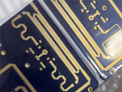
4-layer 0.833mm Rogers RT/duroid 5880 PCB and TG170 FR-4 : Advanced Multi-Layer RF Solution with Green Solder Mask
Printed Circuit Boards are custom-made products; the images and specifications provided are for reference only.
1. Introduction of Rogers RT/duroid 5880 PCB
Rogers RT/duroid 5880 high frequency PCB is a high-performance glass microfiber reinforced PTFE laminate engineered for exacting stripline and microstrip circuit applications. Utilizing randomly oriented microfibers, RT/duroid 5880 PCB material delivers exceptional dielectric constant uniformity, making RT/duroid 5880 circuit board a reliable choice for designs requiring consistent electrical performance across panels and over a wide frequency range.
With its low dissipation factor, Rogers RT/duroid 5880 PCB Board performs reliably into Ku-band and beyond, extending its usefulness in advanced RF and microwave systems.
2. Key PCB Specifications
Parameter |
Specification |
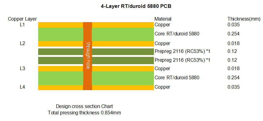
Stack-up Configuration |
4-layer copper, 0.254mm RT5880 + 0.204mm TG170 FR-4 Prepreg + 0.254mm RT5880 |
Finished Thickness |
0.833mm |
Copper Distribution |
Outer Layers: 1OZ (35µm), Inner Layers: 0.5OZ (18µm) |
Board Dimensions |
126mm × 63mm = 1 PCS |
Surface Finish |
Immersion Silver, Solder Mask (Green) without legend |
Minimum Trace/Space |
5mil/5mil |
Via Specification |
Through-hole vias: 0.2mm drill / 0.5mm pad, no blind/buried vias |
3. Material Features and Advantages
Lowest Electrical Loss for Reinforced PTFE Material – Ensures minimal signal attenuation in high-frequency and millimeter-wave applications.
Low Moisture Absorption – Maintains stable performance in varied environmental conditions.
Isotropic Characteristics – Provides uniform mechanical and electrical behavior in all planar directions.
Uniform Electrical Properties Over Frequency – Delivers consistent performance from panel to panel across wide frequency ranges.
Excellent Chemical Resistance – Withstands solvents and reagents used in PCB etching and plating processes.
The material is highly manufacturable—easily cut, sheared, machined—while offering robust chemical resistance throughout fabrication.
4. Material Availability and Cladding Options
Typically supplied with electrodeposited copper cladding ranging from ½ to 2 oz/ft² (8 to 70 µm) or reverse-treated EDC on both sides, Rogers RT/duroid 5880 laminate PCB can also be specified with rolled copper foil for enhanced electrical performance in critical applications. For designs requiring additional mechanical support or thermal management, cladding with aluminum, copper, or brass plates is also available.
- RT/duroid 5880 PCB Datasheet
PROPERTY |
TYPICAL VALUES - RTV/diovid 9370 |
TYPICAL VALUES - RTV/diovid 9480 |
DIRECTION |
UNITS |
CONDITION |
TEST METHOD |
1Dielectric Constant, εr |
2.33 |
2.20 |
Z |
N/A |
CX24/90/50 |
IPC-TM-650 2.5.5.3 |
|
2.33 ± 0.03 spec. |
2.20 ± 0.02 spec. |
Z |
N/A |
8 GHz-40 GHz |
Differential Phase Length |
2Dielectric Constant, εr |
2.33 |
2.20 |
Z |
N/A |
CX24/90/50 |
IPC-TM-650 2.5.5.3 |
|
2.33 ± 0.03 spec. |
2.20 ± 0.02 spec. |
Z |
N/A |
1 MHz-CX24/90/50 |
1 MHz-CX24/90/50 |
Dissipation factor, δ |
0.0003 |
0.0004 |
Z |
N/A |
CX24/90/50 |
IPC-TM-650 2.5.5.5 |
|
0.0005 |
0.0009 |
Z |
N/A |
1 MHz-CX24/90/50 |
1 MHz-CX24/90/50 |
Thermal Coefficient of εr |
-115 |
-125 |
Z |
ppm/°C |
50-150°C |
IPC-TM-650 2.5.5.5 |
Volume Resistivity |
2 x 10¹⁶ |
2 x 10¹⁶ |
Z |
Mohm.cm |
CX24/90/50 |
ASTM D257 |
Surface Resistivity |
2 x 10¹⁷ |
3 x 10¹⁷ |
Z |
Mohm |
CX24/90/50 |
ASTM D257 |
Specific Heat |
0.96(0.23) |
0.96(0.23) |
N/A |
J/kgK (cal/g°C) |
N/A |
Calculated |
Tensile Modulus |
Test at 23°C: 1300 (189)Test at 100°C: 490 (71) |
Test at 23°C: 1070 (156)Test at 100°C: 450 (65) |
X |
MPa (Kpsi) |
N/A |
ASTM D638 |
|
Test at 23°C: 1200 (174)Test at 100°C: 430 (62) |
Test at 23°C: 890 (129)Test at 100°C: 380 (55) |
Y |
MPa (Kpsi) |
N/A |
A |
ultimate stress |
Test at 23°C: 52 (7.5)Test at 100°C: 34 (4.8) |
Test at 23°C: 29 (4.2)Test at 100°C: 18 (2.6) |
X |
MPa (Kpsi) |
N/A |
ASTM D638 |
|
Test at 23°C: 42 (6.1)Test at 100°C: 34 (4.8) |
Test at 23°C: 27 (3.9)Test at 100°C: 17 (2.0) |
Y |
MPa (Kpsi) |
N/A |
A |
ultimate strain |
Test at 23°C: 9.8Test at 100°C: 8.6 |
Test at 23°C: 4.9Test at 100°C: 5.2 |
X |
% |
N/A |
ASTM D638 |
|
Test at 23°C: 10.8Test at 100°C: 8.6 |
Test at 23°C: 6.9Test at 100°C: 7.8 |
Y |
% |
N/A |
A |
Compressive Modulus |
Test at 23°C: 1310 (189)Test at 100°C: 680 (99) |
Test at 23°C: 710 (103)Test at 100°C: 500 (73) |
X |
MPa (Kpsi) |
N/A |
ASTM D695 |
|
Test at 23°C: 1260 (183)Test at 100°C: 660 (96) |
Test at 23°C: 710 (103)Test at 100°C: 500 (73) |
Y |
MPa (Kpsi) |
N/A |
ASTM D695 |
|
Test at 23°C: 890 (129)Test at 100°C: 520 (76) |
Test at 23°C: 490 (71)Test at 100°C: 270 (39) |
Z |
MPa (Kpsi) |
N/A |
ASTM D695 |
ultimate stress |
Test at 23°C: 37 (5.3)Test at 100°C: 25 (3.7) |
Test at 23°C: 29 (4.3)Test at 100°C: 21 (3.1) |
X |
MPa (Kpsi) |
N/A |
A |
|
Test at 23°C: 54 (7.8)Test at 100°C: 39 (5.6) |
Test at 23°C: 52 (7.5)Test at 100°C: 43 (6.2) |
Y |
MPa (Kpsi) |
N/A |
A |
|
Test at 23°C: 40 (5.8)Test at 100°C: 43 (6.3) |
Test at 23°C: 32 (4.6)Test at 100°C: 48 (6.9) |
Z |
MPa (Kpsi) |
N/A |
A |
ultimate strain |
Test at 23°C: 3.3Test at 100°C: 8.7 |
Test at 23°C: 7.7Test at 100°C: 17.8 |
X |
% |
N/A |
ASTM D695 |
|
Test at 23°C: 8.7Test at 100°C: 8.5 |
Test at 23°C: 12.5Test at 100°C: 7.6 |
Y |
% |
N/A |
A |
Moisture Absorption |
0.02 |
0.02 |
N/A |
% |
40°C/11 (4mm) D48/50 |
ASTM D570 |
Thermal Conductivity |
0.22 |
0.20 |
Z |
W/mK |
80°C |
ASTM C518 |
Coefficient of Thermal Expansion |
22 (X)78 (Y)150 (Z) |
31 (X)48 (Y)207 (Z) |
X/Y/Z |
ppm/°C |
0-100°C |
IPC-TM-650 2.4.24.1 |
Density |
500 |
500 |
N/A |
g/cm³ |
N/A |
ASTM D792 |
Tg |
22 |
22 |
N/A |
°C (TMA) |
N/A |
ASTM D3418 |
Copper Peel |
27.2 (4.8) |
31.2 (5.9) |
N/A |
pli (N/mm) |
1oz (35µm) ED/EC after solder float |
IPC-TM-650 2.4.8 |
Flammability |
V-0 |
V-0 |
N/A |
N/A |
N/A |
UL94 |
Lead Free Process Compatible |
Yes |
Yes |
N/A |
N/A |
N/A |
N/A |
6. Technical & Supply Information
Artwork Format: Gerber RS-274-X
Quality Standard: IPC-Class-2
Availability: Worldwide
7. Typical Application Areas
Rogers RT/duroid 5880 4-layer rigid PCB is widely implemented in the following high-performance systems:
Commercial Airline Broadband Antennas
Microstrip and Stripline Circuits
Millimeter Wave Applications
Military Radar Systems
Missile Guidance Systems
Point to Point Digital Radio Antennas
8. Summary
Rogers RT/duroid 5880 printed circuit board provides exceptional dielectric uniformity and low-loss performance in high-frequency applications, supported by its glass microfiber reinforced PTFE construction. With its multi-layer hybrid capability, chemical resistance, and isotropic properties, Rogers RT/duroid 5880 laminate PCB delivers reliable electrical stability for demanding RF systems including millimeter-wave circuits, military radar, and airborne communication platforms.
Founded in 2003, Shenzhen Bicheng Electronics Technology Co., Ltd is an established high frequency PCB supplier and exporter in Shenzhen, China, serving customers worldwide.
We are devoted to delivering high-frequency PCB products and solutions of the highest quality, along with customized service. Get in touch with us to start your project !
Visit https://www.bicheng-enterprise.com to learn more.
Contact Vicky at v.xie@bichengpcb.com to unlock your PCB’s full potential.