


 Home
-
Blog
-
Does the Rogers RO4730G3 Circuit Board Lighten Your Base Station Antenna Without Cutting Performance?
Home
-
Blog
-
Does the Rogers RO4730G3 Circuit Board Lighten Your Base Station Antenna Without Cutting Performance?
Does the Rogers RO4730G3 Circuit Board Lighten Your Base Station Antenna Without Cutting Performance?
 June 23,2026
For engineers designing cellular base station antennas, active antenna arrays, or small cells for 4G, 5G, and IoT applications, every kilogram matters. Heavier antennas require stronger mounting structures, increase wind loading on towers, and drive up shipping and installation costs.
Traditional PTFE-based antenna laminates have served the industry well, but they come with a density penalty. Typical PTFE/glass woven materials have a density around 2.2 g/cm³. For a large array antenna measuring one square meter, that extra density can translate into kilograms of unnecessary weight.
Rogers RO4730G3 laminate offers a fundamentally different approach. But how does it achieve such significant weight reduction without sacrificing the electrical performance that antenna designers demand?
1.The Critical Parameter: Density and Weight Reduction
Density is often overlooked in RF material selection, yet it has direct implications for tower loading, shipping costs, and ease of installation. RO4730G3 PCB laminate incorporates a unique filler system using closed microspheres—hollow glass spheres that displace volume without adding mass. This proprietary formulation gives the material a density of just 1.58 g/cm³, approximately 30 percent lighter than conventional PTFE-based antenna materials.
To put this in perspective, consider a typical base station antenna panel measuring 1000 mm by 500 mm with a 1.5 mm thick laminate. A PTFE-based material at 2.2 g/cm³ would weigh approximately 1.65 kg for the dielectric layer alone. The same volume of Rogers RO4730G3 laminate at 1.58 g/cm³ weighs just 1.19 kg—a saving of nearly 0.5 kg per antenna. For multi-panel installations on a single tower, the cumulative weight reduction becomes substantial.
Table 1: Density Comparison Across Antenna-Grade Laminates
Material |
Typical Density (g/cm³) |
Relative Weight vs. PTFE |
Best Use Case |
Standard PTFE/Glass Woven |
2.20 |
Baseline (100%) |
Traditional antennas |
Competitive Thermoset Antenna Laminate |
1.90 - 2.10 |
86-95% |
Moderate weight reduction |
Rogers RO4730G3 |
1.58 |
72% |
Weight-sensitive 5G arrays |
Rogers RO4725JXR |
1.27 |
58% |
Ultra-lightweight applications |
2.Why Weight Matters for 5G Active Antenna Arrays
The transition to 5G has introduced active antenna arrays where RF components are integrated directly onto the antenna PCB. These active arrays include power amplifiers, low-noise amplifiers, and beamforming ICs—all of which add their own weight and generate heat.
When the base laminate is already heavy, adding active components pushes the total assembly weight even higher. Rogers RO4730G3 laminate starts with a lighter foundation, providing more headroom for active components before reaching tower load limits.
Additionally, lighter antennas experience lower wind loading. For a typical tower installation, every kilogram of antenna mass requires proportional structural support. Reducing antenna weight by 30 percent allows operators to either reduce tower reinforcement costs or install additional antennas on existing structures.
3.What About Electrical Performance? No Compromises
The weight reduction of Rogers RO4730G3 laminate does not come at the expense of RF performance. The material maintains a dielectric constant of 3.00 ± 0.05 at 10 GHz—the value widely favored by antenna designers for its balance between element spacing and bandwidth.
The dissipation factor is 0.0023 at 2.5 GHz and 0.0029 at 10 GHz, ensuring low insertion loss for efficient power transfer from the radio to the radiating elements. Passive intermodulation performance is typically better than -160 dBc, which is critical for multi-carrier base station applications where IM products can desensitize receivers.
Table 2: RO4730G3 Electrical and Mechanical Properties
Parameter |
Typical Value |
Design Significance |
Dielectric Constant at 10 GHz |
3.00 ± 0.05 |
Predictable impedance and element spacing |
Dissipation Factor at 2.5 GHz |
0.0023 |
Low loss for efficient power transfer |
PIM Performance |
≤ -160 dBc |
Suitable for multi-carrier base stations |
Density |
1.58 g/cm³ |
30% lighter than PTFE alternatives |
Z-Axis CTE |
30.3 ppm/°C |
Reliable plated through holes |
UL Flammability Rating |
94 V-0 |
Meets flame retardancy requirements |
4.The Fabrication Advantage of RO4730G3 Laminate
Beyond weight savings, Rogers RO4730G3 laminate offers practical fabrication benefits. Unlike PTFE-based materials that require sodium naphthalene or plasma treatment before copper plating, Rogers RO4730G3 laminate uses a thermoset resin system compatible with standard PCB processes.
Rogers RO4730G3 material supports conventional epoxy processing and high-temperature lead-free solder assembly. The glass transition temperature exceeds 280°C, which provides a wide processing window and excellent plated through hole reliability. The low Z-axis CTE of 30.3 ppm/°C from -55°C to 288°C ensures that vias survive thermal cycling without cracking.
For multilayer constructions, Rogers RO4730G3 substrate is compatible with RO4400 series bondply at 175°C lamination temperatures. This allows designers to build complex layer stacks without investing in specialised PTFE fabrication equipment.
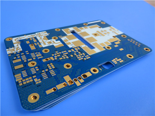
5.Design Recommendations for RO4730G3 Users
For European and North American engineers designing 4G, 5G, or IoT antennas on Rogers RO4730G3 laminate, the following practices will maximise both weight savings and electrical performance.
First, take advantage of the low density in your mechanical design. The 1.58 g/cm³ density allows for thicker laminates without weight penalties. Consider using a 0.76 mm or 1.52 mm core for structural rigidity while keeping total antenna mass lower than a thinner PTFE-based design.
Second, verify your fabricator's experience with thermoset antenna materials. While Rogers RO4730G3 laminate does not require PTFE-specific pre-plating treatments, the drilling parameters differ from standard FR-4. Use new drills and control infeed rates as specified in processing guidelines.
Third, consider hybrid stack-ups if your design requires different Dk values on different layers. Rogers RO4730G3 laminate is fully compatible with the RO4725JXR laminate, allowing designers to mix materials within a single board to optimise feed networks and radiating elements separately.
6.Why Lightweight Laminate Design Matters for Next-Generation Antennas
For European and North American clients designing cellular base station antennas, active antenna arrays, or small cells for 4G and 5G networks, Rogers RO4730G3 laminate delivers a rare combination: significant weight reduction without electrical compromise.
The density of 1.58 g/cm³ makes the Rogers RO4730G3 material approximately 30 percent lighter than traditional PTFE-based antenna laminates, reducing tower loading, shipping costs, and installation effort. The Dk of 3.00 ± 0.05 and Df of 0.0023 at 2.5 GHz provide the low loss and predictable impedance that antenna designers require for high-gain, efficient radiating structures.
The unique closed microsphere filler system enables this weight reduction while maintaining a UL 94 V-0 flame retardancy rating and compatibility with standard lead-free assembly processes. Unlike PTFE alternatives, Rogers RO4730G3 laminate processes like a conventional thermoset, eliminating the need for specialised pre-plating treatments and reducing fabrication cycle times.
If your antenna designs are pushing tower load limits or if you simply want to reduce the installed weight of your next generation of 5G active antenna arrays, Rogers RO4730G3 laminate offers the electrical performance you need with the weight savings your mechanical team will appreciate. The material is available in standard thicknesses including 0.51 mm, 0.76 mm, and 1.52 mm with LoPro copper foil.