


 Home
-
Rogers PCB
-
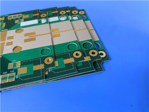
Rogers RT/Duroid 6202 2-Layer PCB 20mil RT/Duroid 6202 High Frequency Circuit Board with ENIG For Radar Phased Array Antenna
Rogers RT/Duroid 6202 2-Layer PCB 20mil RT/Duroid 6202 High Frequency Circuit Board with ENIG For Radar Phased Array Antenna
Printed Circuit Boards are custom-made products; the images and specifications provided are for reference only.
1. Rogers RT/Duroid 6202 PCB Material Introduction
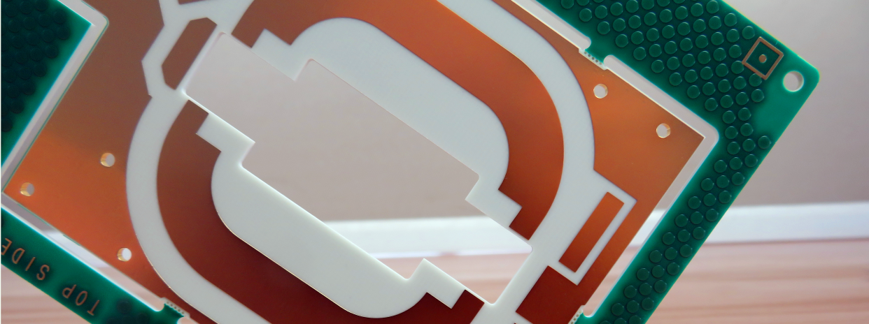
Rogers RT/Duroid 6202 is a high-performance low-loss dielectric laminate engineered for modern microwave and millimeter-wave circuit designs. RT/Duroid 6202 high frequency PCB material adopts a limited woven glass reinforcement structure, balancing ultra-stable electrical performance and reliable mechanical rigidity for complex RF board layouts. Different from fully reinforced glass substrates, the controlled glass content of Rogers RT/Duroid 6202 laminate delivers extremely low etch shrinkage and outstanding dimensional stability, ranging from 0.05 to 0.07 mils per inch. This precise dimensional consistency eliminates the need for double etching processes and enables tight positional tolerances during PCB fabrication. With well-matched electrical parameters and robust mechanical properties, RT/Duroid 6202 RF PCB Bboard maintains stable working performance under variable temperature environments, making it a reliable base material for high-precision radar, antenna and aerospace-grade circuit systems.
2. Core Features of Rogers RT/Duroid 6202 PCB
- Stable Frequency-Dependent Dielectric Constant: Rogers RT/Duroid 6202 PCB features accurate and thickness-adjustable dielectric constant (DK) values tested at 10GHz and 23°C. The 0.005” laminate provides a DK of 3.06 ± 0.04, while 0.010” and 0.015” specifications achieve a DK of 3.02 ± 0.04. All laminate thicknesses above 0.020” maintain a steady DK of 2.94 ± 0.04, ensuring consistent high-frequency signal performance across different board stackup designs.
- Ultra-Low Dissipation Factor: Rogers RT/Duroid 6202 PCB material offers an extremely low dissipation factor (DF) of 0.0015 at 10GHz, minimizing signal attenuation and transmission loss for microwave and RF circuit operation.
- Excellent Thermal Dielectric Stability: Equipped with a low thermal coefficient of dielectric constant at 5 ppm/°C, Rogers RT/Duroid 6202 PCB sustains stable electrical properties within the wide temperature range from -50°C to +150°C.
- Balanced Thermal Expansion Performance: RT/Duroid 6202 laminate delivers well-controlled thermal expansion coefficients from -55°C to 288°C, with 15 ppm/°C for the X-axis, 15 ppm/°C for the Y-axis, and 30 ppm/°C for the Z-axis, ensuring reliable structural stability during processing and long-term operation.
- High Thermal Decomposition Temperature: RT/Duroid 6202 material achieves a TGA decomposition temperature (Td) of 500°C, providing strong heat resistance for high-temperature PCB fabrication and continuous high-power circuit operation.
- Efficient Thermal Conductivity: With a thermal conductivity of 0.68 W/m/k, the substrate effectively dissipates operating heat and prevents thermal accumulation inside compact high-frequency circuit modules.
- Ultra-Low Moisture Absorption: The material features a moisture absorption rate as low as 0.04%, avoiding electrical performance deviation caused by humid working environments.
- Flame Retardant Certification: Compliant with UL 94-V0 flame retardant standards, RT/Duroid 6202 PCB meets safety requirements for commercial, industrial and aerospace electronic applications.
3. Functional Benefits of Rogers RT/Duroid 6202 PCB
- Superior High-Frequency Signal Performance: The low-loss dielectric characteristics significantly reduce signal loss and phase distortion, supporting high-precision signal transmission for microwave and millimeter-wave circuit systems.
- Copper-Matched In-Plane Expansion: The optimized in-plane thermal expansion coefficient is highly matched with copper foil, effectively reducing thermal stress and preventing circuit cracking or layer separation during temperature changes.
- Integrated Electrical & Mechanical Reliability: Combines stable dielectric parameters, rigid structural performance and environmental adaptability to support complex multi-layer and high-density RF circuit designs.
- Minimal Etch Shrinkage Tolerance: Extremely low etching shrinkage simplifies precision circuit patterning, improves line width accuracy, and enhances production yield for high-density fine-trace PCB designs.
4. PCB Construction Details
| Parameter Item | Specific Specifications |
| Base Material | Rogers RT/Duroid 6202 High Frequency Laminate |
| Layer Count | 2-Layer Rigid High Frequency PCB |
| Board Dimensions | 42.36mm x 21.9mm (1PCS) |
| Minimum Trace/Space | 4/7 mils |
| Minimum Hole Size | 0.4mm |
| Blind Vias Design | No Blind Vias |
| Finished Board Thickness | 0.6mm |
| Finished Copper Weight | 1oz (1.4 mils) Outer Layers |
| Via Plating Thickness | 20 μm |
| Surface Finish | ENIG (Electroless Nickel Immersion Gold) |
| Top Silkscreen | White Silkscreen |
| Bottom Silkscreen | No Silkscreen |
| Top Solder Mask | Green Solder Mask |
| Bottom Solder Mask | No Solder Mask |
| Pre-Shipment Test Standard | 100% Electrical Testing Before Shipment |
5. PCB Stackup Structure
Rogers RT/Duroid 6202 2-layer rigid PCB adopts a simple and stable symmetrical stackup structure, ensuring uniform electrical performance and reliable mechanical flatness for high-frequency signal transmission:
- Copper Layer 1 – 35 μm
- Rogers RT/Duroid 6202 Substrate – 20mil (0.508mm)
- Copper Layer 2 – 35 μm
6. PCB Statistical Parameters
The compact circuit layout of this 2-layer Rogers RT/Duroid 6202 PCB meets miniaturized high-frequency assembly requirements with precise component and pad distribution:
- Total Components: 13
- Total Pads: 20
- Thru Hole Pads: 11
- Top SMT Pads: 9
- Bottom SMT Pads: 0
- Total Vias: 6
- Total Nets: 2
7. Production Artwork & Quality Standard
Rogers RT/Duroid 6202 high frequency PCB uses standard Gerber RS-274-X artwork for production, which is universally compatible with global PCB manufacturing equipment. All fabrication and inspection processes strictly comply with IPC-Class-2 quality standards, ensuring consistent product quality and assembly reliability. The product supports worldwide supply and stable mass delivery for global high-frequency communication and radar system projects.
8. Typical Application Fields
Benefiting from ultra-low high-frequency loss, stable dielectric performance and excellent dimensional stability, RT/Duroid 6202 high frequency PCB is widely applied in high-precision military, aerospace and commercial wireless communication systems:
- Phased Array Antenna Systems
- Ground-Based and Airborne Radar Equipment
- GPS Global Positioning Antenna Devices
- High-Frequency Power Backplane Circuits
- Commercial Airborne Collision Avoidance Systems
- Microwave Beam Forming Networks
9. RT/Duroid 6202 DataSheet
| Property | Typical Value | Direction | Units | Conditions | Test Method |
| Dielectric Constant εr | 2.94 ± 0.04 [3] | Z | - | 10GHz/23°C | IPC-TM-650, 2.5.5.5 |
| Dissipation Factor, TAN δ | 0.0015 | Z | - | 10 GHz/23°C | IPC-TM-650, 2.5.5.5 |
| Thermal Coefficient of εr | +5 | Z | ppm/°C | 10 GHz, -50 to +150°C | IPC-TM-650, 2.5.5.5 |
| Volume Resistivity | 106 | Z | Mohm cm | A | ASTM D257 |
| Surface Resistivity | 109 | Z | Mohm | A | ASTM D257 |
| Tensile Modulus | 1007 (146) | X, Y | MPa (kpsi) | 23°C | ASTM D638 |
| Ultimate Stress | 30 (4.3) | X, Y | MPa (kpsi) | - | - |
| Ultimate Strain | 4.9 | X, Y | % | - | - |
| Compressive Modulus | 1035 (150) | Z | MPa (kpsi) | - | ASTM D638 |
| Moisture Absorption | 0.04 | - | % | D23/24, D48/50 | IPC-TM-650, 2.6.2.1; ASTM D570 |
| Thermal Conductivity | 0.68 | - | W/m/K | 80°C | ASTM C518 |
| Coefficient of Thermal Expansion (-55 to 288 °C) | 15 (X),15 (Y),30 (Z) | X,Y,Z | ppm/°C | 23°C/50% RH | IPC-TM-650 2.4.41 |
| Dimensional Stability | 0.07 | X, Y | mm/m (mil/inch) | after etch +E/150 | IPC-TM-650, 2.4.3.9 |
| Td | 500 | - | °C TGA | - | ASTM D3850 |
| Density | 2.1 | - | gm/cm3 | - | ASTM D792 |
| Specific Heat | 0.93 (0.22) | - | J/g/K (BTU/lb/°F) | - | Calculated |
| Copper Peel | 9.1 (1.6) | - | lbs/in (N/mm) | - | IPC-TM-650 2.4.8 |
| Flammability | V-O | - | - | - | UL 94 |
| Lead-Free Process Compatible | YES | - | - | - | - |
10. Rogers RT/Duroid 6202 Copper Clad Laminate Knowledge
Rogers RT/Duroid 6202 high frequency copper clad laminate is a professional low-loss, low dielectric constant substrate material customized for advanced microwave and RF circuit manufacturing. This high-performance CCL material integrates optimized dielectric formula and limited woven glass reinforcement structure, delivering balanced superior electrical stability and solid mechanical reliability for complex high-frequency PCB structures. Different from conventional high-frequency substrates, RT/Duroid 6202 laminate features ultra-precise dimensional stability, effectively supporting high-tolerance fine-line PCB fabrication and simplifying the production process for high-density circuit layouts.
10.1 Core Structural & Processing Characteristics
- Premium Dimensional Stability: With limited woven glass fiber reinforcement, Rogers RT/Duroid 6202 laminate achieves a stable dimensional tolerance of 0.05 to 0.07 mils per inch. This outstanding structural stability removes the need for double etching procedures, enabling ultra-tight positional precision during PCB patterning and improving overall production accuracy.
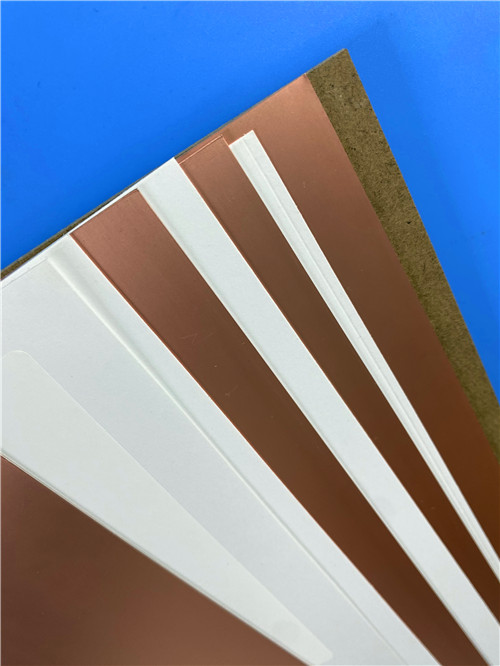
- Flexible Copper Foil Cladding Specification: The RT/Duroid 6202 dielectric substrate supports customizable electrodeposited and rolled copper foil cladding, covering copper weight ranges from 0.5 oz to 2 oz per square foot. It matches diverse dielectric thicknesses from 0.005 inch to 0.060 inch (0.127mm to 1.524mm), fully adapting to various stackup and circuit design requirements of Rogers RT/Duroid 6202 PCB.
- Adaptable Structural Design: This high frequency laminate is highly compatible with flat and non-planar circuit structures, as well as sophisticated multilayer PCBs with interlayer via connections, providing flexible structural solutions for customized microwave circuit designs.
10.2 Key Features & Functional Advantages
- Ultra-Low High-Frequency Loss: The low-loss dielectric property of Rogers RT/Duroid 6202 CCL minimizes signal attenuation at microwave frequency bands, ensuring efficient and stable high-frequency signal transmission for all RF circuit applications.
- Precise DK & Thickness Control: Strict manufacturing tolerance delivers consistent dielectric constant and uniform substrate thickness across the entire board, eliminating electrical performance deviation and ensuring stable batch performance of Rogers RT/Duroid 6202 PCB products.
- Integrated Electrical & Mechanical Superiority: Combines stable dielectric performance, rigid structural strength and excellent environmental adaptability, supporting long-term reliable operation of complex microwave circuit systems.
- Low Thermal Coefficient of Dielectric Constant: The material maintains steady electrical parameters under fluctuating temperature conditions, avoiding frequency drift and performance degradation caused by thermal changes.
- Copper-Matched In-Plane Expansion: Its in-plane thermal expansion coefficient is precisely matched with copper foil, effectively reducing thermal stress and preventing board warpage, cracking or delamination during fabrication and service.
- Minimal Etch Shrinkage Performance: Extremely low etching shrinkage guarantees high-precision line width and spacing consistency, greatly improving production yield for fine-trace Rogers RT/Duroid 6202 high frequency PCB.
10.3 Specialized Application Scenarios
Thanks to the unique low-loss and high-stability properties of Rogers RT/Duroid 6202 copper clad laminate, this material is widely used in high-precision and high-reliability microwave and wireless circuit fields:
- Phased Array Antenna Systems
- Ground Based and Airborne Radar System Equipment
- GPS Global Positioning System Antennas
- High-Frequency Power Backplane Circuits
- High Reliability Complex Multilayer RF Circuits
- Commercial Airline Collision Avoidance Systems
- Microwave Beam Forming Network Modules
11. Summary
Rogers RT/Duroid 6202 high frequency circuit material is a compact and high-reliability rigid microwave circuit board with a 0.6mm finished thickness and premium ENIG surface treatment. Built on 20mil (0.508mm) Rogers RT/Duroid 6202 low-loss laminate, this 2-layer PCB features stable DK/DF parameters, excellent thermal stability and ultra-low etching shrinkage. Equipped with 1oz outer copper layers, standardized 4/7mil fine trace spacing and 100% pre-shipment electrical testing, the board delivers consistent electrical performance and mechanical reliability. With professional green top solder mask and white top silkscreen design, this high frequency PCB fully meets the manufacturing requirements of phased array antennas, radar systems and precision positioning equipment, serving high-performance wireless and microwave system applications worldwide.