


 Home
-
Rogers PCB
-
CLTE-MW 2-Layer 0.2mm Pure Gold High Frequency PCB Rogers Low Loss Microwave Circuit Board
CLTE-MW 2-Layer 0.2mm Pure Gold High Frequency PCB Rogers Low Loss Microwave Circuit Board
Printed Circuit Boards are custom-made products; the images and specifications provided are for reference only.
1. Product Introduction
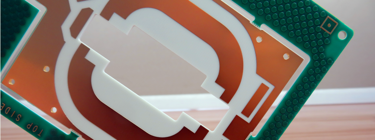
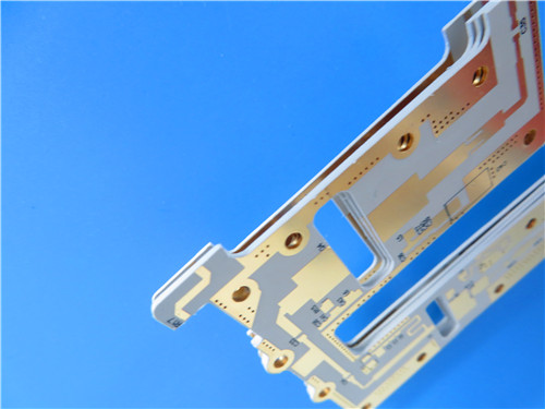
CLTE-MW 2-layer high frequency PCB is a high-performance rigid circuit board engineered for precision millimeter wave and 5G communication applications. This CLTE series PCB adopts premium 0.102 mm CLTE-MW laminate material with spread glass reinforcement and high filler loading, effectively reducing high frequency glass weave interference on electromagnetic wave propagation. Designed with customizable thickness specifications ranging from 3 mils to 10 mils, CLTE-MW circuit board delivers optimal signal-to-ground spacing to meet strict physical and electrical thickness limitation requirements. With pure gold surface finish and standardized IPC-Class-2 manufacturing quality, this CLTE-MW high frequency material provides a cost-effective and reliable circuit solution for commercial, aerospace and military high-frequency electronic systems, supporting stable operation in complex thermal and electromagnetic environments.
2. Core Product Features
- Extremely low loss tangent of 0.0015 at 10GHz, ensuring stable high-frequency signal transmission
- Low Z-axis CTE of 30ppm/°C, optimizing structural stability during temperature changes
- Superior thermal conductivity of 0.42 W/(mK) for efficient heat transfer
- Complies with UL94 V-0 flammability rating, meeting global safety fire resistance standards
- Precision circuit design with 4/6 mils minimum trace/space and 0.3mm minimum hole size
- Standard 2-layer rigid structure without blind vias, simplifying assembly and improving structural stability
3. Product Performance Benefits
- Supports ultra-low loss circuit designs, minimizing high-frequency signal attenuation for 5G and millimeter wave devices
- Offers excellent plated through hole (PTH) reliability, ensuring long-term structural and electrical stability
- Achieves outstanding heat dissipation performance, adapting to high-load and aggressive circuit design scenarios
- Features strong compatibility with various commercial communication electronic applications, reducing application adaptation costs
- Maintains consistent mechanical performance under thermally challenging and high-temperature working environments
4. PCB Construction Details
| Parameter Item | Technical Specification |
| Board Dimensions | 35.8mm x 66.5mm (1PCS), Tolerance: +/- 0.15mm |
| Minimum Trace/Space | 4/6 mils |
| Minimum Hole Size | 0.3mm |
| Blind Vias Design | No Blind Vias |
| Finished Board Thickness | 0.2mm |
| Finished Copper Weight (Outer Layers) | 1oz (1.4 mils) |
| Via Plating Thickness | 20 μm |
| Surface Finish | Pure Gold |
| Top Silkscreen | White |
| Bottom Silkscreen | No Silkscreen |
| Top Solder Mask | Green |
| Bottom Solder Mask | No Solder Mask |
| Pre-Shipment Testing | 100% Electrical Test |
5. PCB Stackup Structure
0.102mm CLTE-MW laminate PCB adopts a standard 2-layer rigid PCB stackup structure with stable and layered layout, which ensures uniform signal transmission and reliable structural performance. The detailed stackup configuration is as follows:
- Copper_layer_1: 35 μm
- CLTE-MW Core: 0.102 mm (4.016mil)
- Copper_layer_2: 35 μm
6. PCB Statistical Parameters
- Components: 43
- Total Pads: 27
- Thru Hole Pads: 19
- Top SMT Pads: 8
- Bottom SMT Pads: 0
- Vias: 25
- Nets: 6
7. Artwork Supplied Type
The PCB design artwork is provided in Gerber RS-274-X standard format, which is universally compatible with global PCB manufacturing and processing equipment, supporting accurate circuit etching and production.
8. Quality Manufacturing Standard
CLTE-MW 0.2mm Thickness PCB is manufactured in strict accordance with IPC-Class-2 industry quality standards, ensuring consistent product quality, stable electrical performance and qualified structural reliability for industrial and commercial applications.
9. Product Availability
2-layer CLTE-MW high frequency PCB is available for worldwide supply, supporting global customer procurement and customized processing services.
10. Typical Application Scenarios
- Commercial Communications and Avionics Systems
- Military and Aerospace Electronic Equipment
- Microwave Feed Network Devices
- Phase Sensitive Electronic Structures
- Satellite Communication Systems
- Passive Components Including Couplers, Filters and Baluns
11.CLTE Copper Clad Laminate (CCL) Knowledge
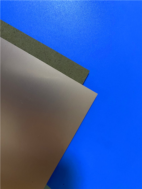
CLTE series high frequency copper clad laminates are core dielectric materials specially developed for high-performance radio frequency, microwave and millimeter wave PCB production. As a premium PTFE-based laminate solution, CLTE materials stand out in the high-frequency circuit industry for their ultra-stable physical and electrical properties, serving as the foundational guarantee for the reliable operation of CLTE-MW high frequency PCB boards.
11.1 Core Material Advantages
- Superior Dimensional Stability: CLTE laminates feature ultra-low planar CTE and excellent dimensional uniformity, delivering extremely low performance variance among all PTFE-based copper clad laminates. This stable property enables high-precision integration of embedded resistors and fine-line circuits on high frequency PCBs.
- Diversified Cladding Compatibility: With mature and stable application experience matching resistor foil, CLTE laminates support multiple copper cladding options, including electrodeposited copper, reverse treated copper and rolled copper foil, meeting diverse high-frequency PCB design and manufacturing demands.
- Proven Industrial Reliability: After long-term market verification, CLTE copper clad laminates have become the preferred dielectric material for ground-based and airborne communication equipment, as well as high-precision radar system PCBs, with stable performance in complex working conditions.
11.2 Key Features and Corresponding Performance Benefits
- Ultra-Low Loss Tangent: Boasts a loss tangent of 0.0012 at 10 GHz, effectively reducing high-frequency circuit signal loss while maintaining outstanding dimensional stability, maximizing the signal transmission efficiency of high frequency PCB.
- Ultra-Low Z-axis CTE: Equipped with a low Z-axis CTE of 20 ppm/°C, greatly improves the structural stability of plated through holes, effectively avoiding hole cracking and circuit failure caused by temperature cycling, and enhancing the long-term reliability of multilayer and precision PCBs.
- Temperature-Stable Dielectric Constant: The dielectric constant remains stable under varying temperature environments, reducing thermal stress on ceramic active devices mounted on the high frequency PCB, and protecting core electronic components.
- Heavy Metal Backing Support: Customizable with aluminum, brass and copper heavy metal backing structures, perfectly adapting to embedded resistor network design requirements and improving the structural firmness and heat resistance of high-frequency circuit boards.
11.3 Extended Application Scenarios of CLTE Laminate PCB
- Advanced Driver Assistance Systems (ADAS) automotive high-frequency circuit modules
- High-precision patch antenna PCBs for wireless communication devices
- Phased array antenna system high-frequency microwave circuit boards
- High-power amplifier RF PCBs for communication base stations
- 12.CLTE Series Laminates Data Sheet
| Properties | Typical Values1 | Units | Test Conditions | Standard | |
| Dielectric Constant (process) | 2.98 | - | 23˚C @ 50% RH, 10 GHz | IPC TM-650 2.5.5.5 | |
| Dielectric Constant (design) | 2.98 | - | C-24/23/50, 10 GHz | Microstrip Differential Phase Length | |
| Dissipation Factor | 0.0021 | - | 23˚C @ 50% RH, 10 GHz | IPC TM-650 2.5.5.5 | |
| Thermal Coefficient of Dielectric Constant | 6 | ppm/˚C | -50 to 150˚C, 10 GHz | IPC TM-650 2.5.5.5 | |
| Volume Resistivity | 1.4 X 10⁹ | Mohm-cm | C-96/35/90 | - | IPC TM-650 2.5.17.1 |
| Surface Resistivity | 1.30 X 10⁶ | Mohm | C-96/35/90 | - | IPC TM-650 2.5.17.1 |
| Electrical Strength (dielectric strength) | 1100 | V/mil | - | - | IPC TM-650 2.5.6.2 |
| Dielectric Breakdown | 64 | kV | D-48/50, X/Y Direction | IPC TM-650 2.5.6 | |
| PIM | - | dBc | 50 ohm 0.060", 43dBm 1900 MHz | - | |
| Decomposition Temperature (Td) | 538 | ˚C | 2hrs @ 105˚C, 5% Weight Loss | IPC TM-650 2.3.40 | |
| Coefficient of Thermal Expansion - x | 9.9 | ppm/˚C | -55˚C to 288˚C | IPC TM-650 2.4.41 | |
| Coefficient of Thermal Expansion - y | 9.4 | ppm/˚C | -55˚C to 288˚C | IPC TM-650 2.4.41 | |
| Coefficient of Thermal Expansion - z | 57.9 | ppm/˚C | -55˚C to 288˚C | IPC TM-650 2.4.41 | |
| Thermal Conductivity | 0.5 | W/(m.K) | z direction | ASTM D5470 | |
| Time to Delamination | >60 | minutes | as-received, 288˚C | IPC TM-650 2.4.24.1 | |
| Copper Peel Strength after Thermal Stress | 1.2 (7) | N/mm (lbs/in) | 10s @288˚C, 35 μm foil | IPC TM-650 2.4.8 | |
| Flexural Strength (MD, CMD) | 92.4, 86.9 (13.4, 12.6) | MPa (ksi ) | 25˚C ± 3˚C | - | ASTM D790 |
| Tensile Strength (MD, CMD) | 73.8, 71.0 (10.7, 10.3) | MPa (ksi ) | 23C/50RH | - | ASTM D638 |
| Flex Modulus (MD, CMD) | 8122, 7984 (1178, 1158) | MPa (ksi ) | 25˚C ± 3˚C | - | ASTM D790 |
| Dimensional Stability (MD, CMD) | -0.07, -0.02 | mm/m | 4 hr at 105˚C | - | IPC-TM-650 2.4.39a |
| Flammability | V-0 | - | C48/23/50 & C168/70 | UL 94 | |
| Moisture Absorption | 0.04 | % | E1/105+D24/23 | - | IPC TM-650 2.6.2.1 |
| Density | 2.31 | g/cm³ | C-24/23/50 | - | ASTM D792 |
| Specific Heat Capacity | 0.60 | J/g˚K | 2 hours at 105˚C | - | ASTM E2716 |
| NASA Outgassing Total Mass Lost | 0.02 | % | - | ASTM E595 | |
| NASA Outgassing Collected Volatiles | 0.00 | % | - | - |
13.Product Summary
CLTE-MW high frequency PCB is a premium low-loss rigid circuit board tailored for high-frequency millimeter wave and 5G communication industries. Featuring 0.2mm ultra-thin finished thickness, pure gold surface finish and CLTE-MW high-performance laminate core material, this PCB achieves ultra-low loss tangent at 10GHz, excellent thermal conductivity and stable thermal expansion performance. With standardized IPC-Class-2 manufacturing quality and precise circuit parameters, it delivers reliable low-loss signal transmission, superior heat dissipation and durable mechanical performance, fully adapting to commercial communication, aerospace, military and satellite communication high-precision electronic device applications.