

 Home
-
Newly shipped PCBs
-
Rogers RT/duroid 6002 30mil Double-layer PCB Low Loss PCB for Microwave and Radar Applications
Home
-
Newly shipped PCBs
-
Rogers RT/duroid 6002 30mil Double-layer PCB Low Loss PCB for Microwave and Radar Applications
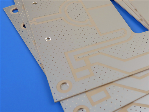
Rogers RT/duroid 6002 30mil Double-layer PCB Low Loss PCB for Microwave and Radar Applications
Printed Circuit Boards are custom-made products; the images and specifications provided are for reference only.
1. Rogers RT/duroid 6002 PCB Introduction
Rogers RT/duroid 6002 2-Layer High Frequency PCB is a high-performance rigid printed circuit board engineered with Rogers RT/duroid 6002 ceramic-filled PTFE microwave laminate, specifically designed for complex microwave and high-frequency applications. This 0.8mm thick 2-layer PCB integrates the advanced properties of RT/duroid 6002 substrate, including low dielectric constant, ultra-low loss, and excellent mechanical and electrical stability, making it reliable for multi-layer board constructions. With Immersion Silver surface finish, precise dimensional control, and compliance with IPC-Class-2 standards, it delivers consistent performance in demanding environments, making it an ideal solution for phased array antennas, radar systems, GPS antennas, and aerospace microwave circuits.
2. Rogers RT/duroid 6002 PCB Features
- Dielectric Constant (Dk): 2.94 +/- 0.04, ensuring stable signal transmission in complex microwave structures
- Thermal Coefficient of Dk: 12 ppm/℃, providing excellent electrical stability across temperature ranges
- Dissipation Factor (Df): 0.0012 at 10GHz, enabling ultra-low loss and superior high-frequency performance
- Decomposition Temperature (Td): 500℃ (TGA), ensuring high-temperature stability
- Thermal Conductivity: 0.6 W/m·K, facilitating efficient heat dissipation
- Z-axis Coefficient of Thermal Expansion (CTE): 24 ppm/℃, ensuring excellent PTH reliability
- Moisture Absorption: 0.02%, minimizing environmental impact on performance
- Flammability Rating: UL 94-V0, complying with safety standards
- Excellent Dimensional Stability: 0.2 to 0.5 mils/inch, supporting tight positional tolerances
- In-plane CTE Matched to Copper, reducing stress on solder joints and enhancing surface mount reliability
3. Rogers RT/duroid 6002 PCB Benefits
- Ultra-Low Loss: Delivers excellent high-frequency performance, ideal for microwave and RF applications
- Tight Thickness Control: Ensures consistent performance and compatibility with precision designs
- Temperature Stability: In-plane CTE matched to copper, making it ideal for temperature-sensitive applications
- Low Out-Gassing: Suitable for space and aerospace applications requiring high reliability
- Superior Dimensional Stability: Eliminates the need for double etching to achieve tight positional tolerances
- Excellent Mechanical & Electrical Properties: Enables reliable multi-layer board constructions
- High PTH Reliability: Low Z-axis CTE ensures plated through-holes withstand over 5000 temperature cycles (-55℃ to 125℃) without failure
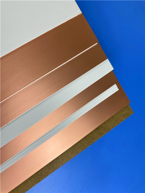
- Versatile Cladding Options: Compatible with various copper types and thicknesses, as well as aluminum, brass, or resistive foils
4. PCB Construction Details
Construction Item |
Specification |
Base Material |
RT/duroid 6002 |
Layer Count |
2 Layers |
Board Dimensions |
156mm x 87.9mm = 1PCS |
Minimum Trace/Space |
6/7 mils |
Minimum Hole Size |
0.3mm |
Blind Vias |
No |
Finished Board Thickness |
0.8mm |
Finished Cu Weight (Outer Layers) |
1 oz (1.4 mils) |
Via Plating Thickness |
20 μm |
Surface Finish |
Immersion Silver |
Top Silkscreen |
No |
Bottom Silkscreen |
No |
Top Solder Mask |
No |
Bottom Solder Mask |
No |
Pre-Shipment Electrical Test |
100% Electrical Test Used |
5. PCB Stackup
2-layer rigid PCB, with the following layer structure (from top to bottom):
- Copper_layer_1 - 35 μm
- Rogers RT/duroid 6002 Substrate - 30mil (0.762mm)
- Copper_layer_2 - 35 μm
6. PCB Statistics
- Components: 94
- Total Pads: 241
- Thru Hole Pads: 196
- Top SMT Pads: 45
- Bottom SMT Pads: 0
- Vias: 126
- Nets: 2
7. Artwork Format
Gerber RS-274-X, the industry-standard format for PCB fabrication, ensuring compatibility with most manufacturing equipment and processes.
8. Quality Standard
Complies with IPC-Class-2 standards, guaranteeing consistent quality, reliability, and performance for commercial, industrial, and high-tech applications.
9. Global Availability
Available worldwide, supported by reliable supply chains to meet global customers’ production needs and ensure timely delivery.
10. Typical Applications
- Phased Array Antennas
- Ground Based and Airborne Radar Systems
- Global Positioning System (GPS) Antennas
- Power Backplanes
- Commercial Airline Collision Avoidance Systems
- Beam Forming Networks
- Aerospace Microwave Circuits for Hostile Environments
11. Rogers RT/duroid 6002 CCL Introduction
Rogers RT/duroid® 6002 is a high-frequency ceramic-filled PTFE laminate, the first low-loss, low-dielectric-constant material to offer superior electrical and mechanical properties essential for designing complex, mechanically reliable, and electrically stable microwave structures. It maintains an extremely low thermal coefficient of dielectric constant from -55℃ to +150℃, providing the electrical stability required for filters, oscillators, and delay lines in demanding applications.
11.1 CCL Core Properties
- Ceramic-filled PTFE composition, delivering low dielectric constant (2.94 +/- 0.04) and ultra-low loss (Df = 0.0012 at 10GHz)
- Extremely low thermal coefficient of Dk (12 ppm/℃) from -55℃ to +150℃, ensuring electrical stability across temperature ranges
- Low Z-axis CTE (24 ppm/℃) and in-plane CTE matched to copper, enhancing PTH reliability and dimensional stability
- Excellent dimensional stability (0.2 to 0.5 mils/inch), eliminating the need for double etching
- Low tensile modulus (X,Y), reducing stress on solder joints and improving surface mount reliability
- Moisture absorption of 0.02% and low out-gassing, suitable for space and harsh environment applications
- UL 94-V0 flammability rating, complying with safety standards
11.2 CCL Key Advantages
- Ultra-Low Loss: Enables excellent high-frequency performance, critical for microwave and RF applications
- Superior PTH Reliability: Withstands over 5000 temperature cycles (-55℃ to 125℃) without via failure
- Versatile Cladding: Available with ½ oz. to 2 oz./ft² electrodeposited/rolled copper, reverse treated copper, as well as aluminum, brass, or resistive foils
- Broad Dielectric Thickness Range: 0.005” to 0.125” (0.13 to 3.18mm), adapting to diverse design needs
- Mechanical Reliability: Excellent mechanical and electrical properties, supporting complex multi-layer board constructions
- Temperature Resilience: Stable performance in extreme temperature ranges, ideal for aerospace and defense applications
11.3 CCL Application Suitability
- Ideal for flat and non-planar structures, including antennas and complex multi-layer circuits with inter-layer connections
- Suitable for aerospace microwave circuits in hostile environments, thanks to low out-gassing and temperature stability
- Perfect for applications requiring tight positional tolerances, such as filters, oscillators, and delay lines
- Well-suited for radar systems, GPS antennas, and beam forming networks due to low loss and dimensional stability
12. DataSheet
Property |
Typical Value |
Direction |
Units |
Conditions |
Test Method |
Dielectric Constant (εr, Process) |
2.94 ± 0.04 |
Z |
– |
10 GHz / 23°C |
IPC-TM-650 2.5.5.5 |
Dielectric Constant (εr, Design) |
2.94 |
– |
– |
8 GHz – 40 GHz |
Differential Phase Length Method |
Dissipation Factor (Tan δ) |
0.0012 |
Z |
– |
10 GHz / 23°C |
IPC-TM-650 2.5.5.5 |
Thermal Coefficient of εr |
+12 |
Z |
ppm/°C |
10 GHz, 0–100°C |
IPC-TM-650 2.5.5.5 |
Volume Resistivity |
10⁶ |
Z |
MΩ·cm |
A |
ASTM D257 |
Surface Resistivity |
10⁷ |
Z |
MΩ |
A |
ASTM D257 |
Tensile Modulus |
828 (120) |
X,Y |
MPa (kpsi) |
23°C |
ASTM D638 |
Ultimate Stress |
6.9 (1.0) |
X,Y |
MPa (kpsi) |
– |
– |
Ultimate Strain |
7.3 |
X,Y |
% |
– |
– |
Compressive Modulus |
2482 (360) |
Z |
MPa (kpsi) |
– |
ASTM D638 |
Moisture Absorption |
0.02 |
– |
% |
D48/50 |
IPC-TM-650 2.6.2.1, ASTM D570 |
Thermal Conductivity |
0.60 |
– |
W/m/K |
80°C |
ASTM C518 |
CTE (-55 to 288°C) |
16 |
X |
ppm/°C |
23°C / 50% RH |
IPC-TM-650 2.4.41 |
|
16 |
Y |
ppm/°C |
|
|
|
24 |
Z |
ppm/°C |
|
|
Decomposition Temperature (Td) |
500 |
– |
°C |
TGA |
ASTM D3850 |
Density |
2.1 |
– |
g/cm³ |
– |
ASTM D792 |
Specific Heat |
0.93 (0.22) |
– |
J/g/K (BTU/lb/°F) |
– |
Calculated |
Copper Peel Strength |
8.9 (1.6) |
– |
lbs/in (N/mm) |
– |
IPC-TM-650 2.4.8 |
Flammability |
V-0 |
– |
– |
– |
UL 94 |
Lead-Free Process Compatible |
YES |
– |
– |
– |
– |
13. Summary
Rogers 2-Layer RT/duroid 6002 High Frequency PCB is a high-reliability, low-loss solution tailored for complex microwave, RF, and aerospace applications. This 0.8mm thick 2-layer PCB leverages Rogers’ RT/duroid 6002 CCL, delivering stable electrical performance, excellent dimensional stability, and superior PTH reliability. With Immersion Silver surface finish, compliance with IPC-Class-2 standards, and compatibility with various cladding options, it is optimized for demanding applications such as phased array antennas, radar systems, and space equipment. Widely available worldwide, it provides consistent performance and value for high-tech industries requiring ultra-low loss and temperature-stable PCB solutions.