


 Home
-
Newly shipped PCBs
-
RO4003C High Frequency PCB Built on Rogers 20mil Substrate with TG170 FR4 for Base Station Antennas and Automotive Radar
Home
-
Newly shipped PCBs
-
RO4003C High Frequency PCB Built on Rogers 20mil Substrate with TG170 FR4 for Base Station Antennas and Automotive Radar
RO4003C High Frequency PCB Built on Rogers 20mil Substrate with TG170 FR4 for Base Station Antennas and Automotive Radar
Printed Circuit Boards are custom-made products; the images and specifications provided are for reference only.
1. RO4003C 6-Layer PCB Overview
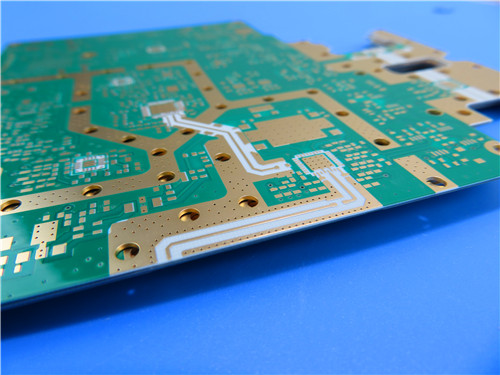
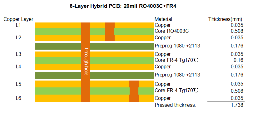
This Rogers 6-layer hybrid high-frequency PCB is built with a composite stackup combining RO4003C hydrocarbon ceramic laminate, TG170℃ FR4 prepreg, and TG170℃ FR4 substrate, delivering a finished pressed thickness of 1.74mm. The board dimension is 127mm × 103mm (1 piece, including process edge), with a uniform 1oz finished copper weight applied to all six conductive layers. Both top and bottom surfaces feature green solder mask paired with clear white silkscreen legend, and RO4003C PCB is finished with hard gold plating to ensure reliable electrical contact and wear resistance.
Engineered for high-precision RF and microwave circuit requirements, Rogers RO4003C multilayer PCB supports two sets of blind via structures (L1-L2 and L5-L6) and strict impedance control design. All plated through holes comply with IPC-Class-3 high-reliability specifications with a minimum 25μm hole copper thickness, ensuring exceptional structural durability, thermal shock resistance, and long-term operational stability. By combining the low-loss high-frequency performance of RO4003C material with the mature processability of standard FR4, Rogers RO4003C hybrid PCB balances cost efficiency and performance, making it ideal for cellular base station antennas, automotive radar systems, and satellite communication applications.
2.RO4003C 6-Layer Hybrid PCB Construction
Specification Item |
Technical Details & Standard |
Layer Count |
6-Layer Hybrid High-Frequency Rigid PCB |
Stackup Configuration |
RO4003C core laminate + TG170℃ FR4 prepreg + TG170℃ FR4 substrate |
Finished Pressed Thickness |
1.74mm |
Board Dimension & Quantity |
127mm × 103mm (1PCS, including process edge) |
Full Layer Copper Weight |
1oz (35μm) Finished Copper per Layer |
Hole Copper Thickness |
25μm (IPC-Class-3 High Reliability Standard) |
Special Process |
Blind vias (L1-L2, L5-L6) + Custom impedance control |
Surface Finish |
Hard Gold Plating |
Solder Mask |
Top & Bottom Green Solder Mask |
Silkscreen |
Top & Bottom White Legend |
Fabrication Standard |
IPC-Class-3 High-Reliability Specification |
Artwork Format |
Gerber RS-274-X |
3. Professional PCB Stackup Structure
Rogers 6-layer hybrid PCB adopts a scientific composite stackup combining RO4003C high-frequency hydrocarbon ceramic laminate and TG170℃ FR4 dielectric materials. The layered configuration optimizes high-frequency electrical performance while maintaining excellent mechanical rigidity and standard FR4 process compatibility, perfectly adapting to impedance-controlled microwave circuit designs.

4. Core Manufacturing & Process Advantages
- Hybrid High-Frequency Design: Integrates RO4003C low-loss high-frequency material and standard TG170℃ FR4, achieving a perfect balance between superior RF performance and cost-effective FR4 processing.
- Dual Blind Via Structure: L1-L2 and L5-L6 blind via designs enable high-density circuit routing, reducing signal path length and improving high-frequency signal integrity.
- IPC-Class-3 Ultra-High Reliability: 25μm thick hole copper enhances hole wall adhesion and thermal shock resistance, preventing delamination and barrel cracking during long-term high-temperature operation.
- Precision Impedance Control: Custom impedance calibration eliminates signal attenuation and phase deviation, ensuring stable high-speed signal transmission for RF and microwave applications.
- Hard Gold Surface Finish: Delivers excellent electrical conductivity, wear resistance, and contact reliability, suitable for high-cycle plug-and-play and high-power RF applications.
- Universal Process Compatibility: Fabricated using standard FR4 production workflows, supporting dense vias, fine traces, and mass production with consistent quality.
5. Introduction of RO4000® Series & RO4003C Copper Clad Laminate
Rogers RO4000® series hydrocarbon ceramic laminates are premium high-frequency circuit materials developed by Rogers Corporation, designed to deliver superior high-frequency performance while enabling cost-effective PCB fabrication using standard FR4 processing techniques. Unlike traditional PTFE-based high-frequency materials, RO4000 series laminates do not require specialized sodium etch via preparation, making them ideal for high-volume manufacturing applications.
Rogers RO4000 series circuit material is widely recognized for its excellent electrical properties, including low dielectric loss, tight dielectric constant tolerance, and stable performance across a broad frequency range. These characteristics make it a preferred choice for RF microwave circuits, matching networks, and controlled impedance transmission lines, especially for applications operating at 500 MHz and above. RO4000 materials feature one of the lowest thermal coefficients of dielectric constant in the industry, ensuring consistent electrical performance even under varying temperature conditions.
The RO4003C™ variant, a core member of the RO4000 series, is available in configurations using both 1080 and 1674 glass fabric styles, all meeting the same strict electrical performance specifications. Specifically designed as a drop-in replacement for legacy high-frequency materials, RO4003C conforms to the requirements of IPC-4103 slash sheet /10. The material is reinforced with hydrocarbon/ceramic composites (not PTFE), offering superior dimensional stability, low thermal expansion, and excellent plated through-hole reliability. With a glass transition temperature (Tg) exceeding 280°C, RO4003C laminate PCB maintains stable expansion characteristics throughout the entire circuit processing temperature range, making it suitable for severe thermal shock applications.
6. Key Performance Features of RO4003C Material
- Low Loss High-Frequency Performance: Low dielectric loss tangent minimizes signal attenuation, making it ideal for broadband and high-frequency RF applications.
- Stable Electrical Properties: Tight dielectric constant tolerance and stable performance across a broad frequency range enable repeatable filter designs and consistent impedance control.
- Ultra-Low Thermal Coefficient of Dielectric Constant: Maintains stable electrical performance under varying temperatures, reducing signal drift in temperature-sensitive applications.
- Copper-Matched Thermal Expansion: Low in-plane and Z-axis CTE closely match copper foil, ensuring excellent dimensional stability and reliable plated through-hole quality, even in severe thermal shock environments.
- High Glass Transition Temperature: Tg >280°C, maintaining stable expansion characteristics throughout the entire circuit processing temperature range.
- Standard FR4 Process Compatibility: No specialized via preparation required, compatible with standard FR4 fabrication techniques and automated handling systems, significantly reducing production complexity and cost.
- Volume Manufacturing Process: Mature mass-production process supports high-volume manufacturing with consistent quality and competitive pricing.
- CAF Resistant: Excellent resistance to conductive anodic filament growth, preventing circuit failure caused by electrochemical migration in high-humidity environments.
- Drop-In Replacement Compatibility: Conforms to IPC-4103 /10 standards, designed as a direct replacement for legacy RO4003C materials, simplifying design upgrades.
7. Typical Application Fields
With its low-loss performance, excellent thermal stability, and standard FR4 processability, RO4000 series laminates (including RO4003C) are widely deployed in high-frequency and high-reliability applications:
- Cellular base station antennas and power amplifiers
- RF identification (RFID) tags and readers
- Automotive radar systems and advanced driver-assistance sensors
- Low-noise block downconverters (LNBs) for direct broadcast satellites
- Microwave communication modules and phased array antenna systems
- Controlled impedance transmission lines and high-speed signal processing circuits
8.Rogers RO4003C Datasheet
Property |
Typical Value |
Direction |
Units |
Condition |
Test Method |
Dielectric Constant (εr), Process |
3.38 ± 0.05 |
Z |
– |
10 GHz / 23°C |
IPC-TM-650 2.5.5.5 (Clamped Stripline) |
Dielectric Constant (εr), Design |
3.55 |
Z |
– |
8 to 40 GHz |
Differential Phase Length Method |
Dissipation Factor (tan δ) |
0.00270.0021 |
Z |
– |
10 GHz / 23°C2.5 GHz / 23°C |
IPC-TM-650 2.5.5.5 |
Thermal Coefficient of εr |
+40 |
Z |
ppm/°C |
-50°C to 150°C |
IPC-TM-650 2.5.5.5 |
Volume Resistivity |
1.7 × 10¹⁰ |
– |
MΩ•cm |
COND A |
IPC-TM-650 2.5.17.1 |
Surface Resistivity |
4.2 × 10⁹ |
– |
MΩ |
COND A |
IPC-TM-650 2.5.17.1 |
Electrical Strength |
31.2 (780) |
Z |
kV/mm (V/mil) |
0.51 mm (0.020") |
IPC-TM-650 2.5.6.2 |
Tensile Modulus |
19650 (2850)19450 (2821) |
XY |
MPa (ksi) |
Room Temperature (RT) |
ASTM D638 |
Tensile Strength |
139 (20.2)100 (14.5) |
XY |
MPa (ksi) |
Room Temperature (RT) |
ASTM D638 |
Flexural Strength |
276 (40) |
– |
MPa (kpsi) |
– |
IPC-TM-650 2.4.4 |
Dimensional Stability |
<0.3 |
X, Y |
mm/m (mils/inch) |
After etch +E2 / 150°C |
IPC-TM-650 2.4.39A |
Coefficient of Thermal Expansion |
111446 |
XYZ |
ppm/°C |
-55°C to 288°C |
IPC-TM-650 2.4.41 |
Glass Transition Temperature (Tg) |
>280 |
– |
°C (TMA) |
Condition A |
IPC-TM-650 2.4.24.3 |
Decomposition Temperature (Td) |
425 |
– |
°C (TGA) |
– |
ASTM D3850 |
Thermal Conductivity |
0.71 |
– |
W/m·K |
80°C |
ASTM C518 |
Moisture Absorption |
0.06 |
– |
% |
48 hrs immersion, 0.060" sample, 50°C |
ASTM D570 |
Density |
1.79 |
– |
g/cm³ |
23°C |
ASTM D792 |
Copper Peel Strength |
1.05 (6.0) |
– |
N/mm (pli) |
After solder float, 1 oz EDC Foil |
IPC-TM-650 2.4.8 |
Flammability |
N/A |
– |
– |
– |
UL 94 |
Lead-Free Process Compatible |
Yes |
– |
– |
– |
– |
9. Rogers RO4003C 6-Layer PCB Overall Summary
Rogers RO4003C 6-Layer 1.74mm Hard Gold PCB is a high-performance hybrid high-frequency rigid circuit board built with premium RO4003C hydrocarbon ceramic laminate and TG170℃ FR4 materials. Featuring full-layer 1oz copper, hard gold plating, dual-side green solder mask and white silkscreen, RO4003C PCB adopts IPC-Class-3 25μm hole copper standard, dual blind via structures (L1-L2, L5-L6), and custom impedance control design. Benefiting from RO4003C material’s low dielectric loss, ultra-stable electrical properties, copper-matched CTE, and standard FR4 process compatibility, it delivers reliable dimensional accuracy and consistent RF performance in high-temperature and long-term operating environments. Ideal for cellular base station antennas, automotive radar systems, satellite communication devices, and other high-frequency applications, RO4003C 6-layer customized PCB provides a cost-effective, high-performance solution for modern RF and microwave industries.
Tags: Rogers RO4003C PCB, RO4003C 6-Layer Hybrid PCB, RO4003C and FR4 PCB, RO4003C High-Frequency PCB, Hard Gold Plated PCB, Rogers RO4000 Series PCB, RO4003C 20mil PCB, Blind Via PCB, IPC-Class-3 PCB, Impedance Controlled RF PCB, Cellular Base Station Antenna PCB, Automotive Radar PCB, Satellite Communication LNB PCB, Standard FR4 Processable PCB, CAF Resistant PCB