


 Home
-
Hybrid PCB
-
RO3003 6-Layer Hybrid PCB 5mil Rogers RO3003 and 5mil Isola 370HR ENIG PCB For Automotive Radar & Antenna
RO3003 6-Layer Hybrid PCB 5mil Rogers RO3003 and 5mil Isola 370HR ENIG PCB For Automotive Radar & Antenna
Printed Circuit Boards are custom-made products; the images and specifications provided are for reference only.
1. Introduction
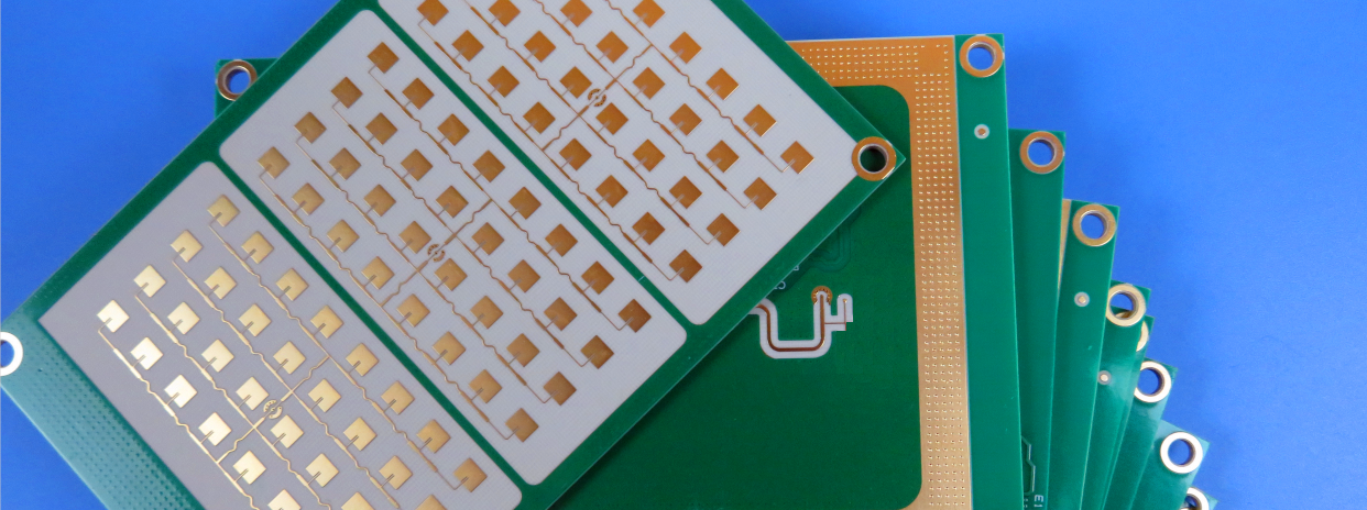
RO3003 6-layer hybrid PCB is a rigid multilayer high-frequency printed circuit board constructed with 5mil RO3003 ceramic-filled PTFE laminate and 5mil Isola 370HR FR4 prepreg. RO3003 high frequency PCB adopts mixed dielectric stackup design, combining high-performance RO3003 RF substrate and high Tg 370HR bonding material. With a total laminated thickness of 0.82mm, RO3003 rigid PCB balances low microwave insertion loss, mechanical reliability and mass production cost. 6-layer 5mil RO3003 PCB features 1oz outer copper, 0.5oz inner copper, blue solder mask paired with white top silkscreen and immersion gold surface finish. RO3003 PCB board structure includes 1-2 blind vias, 0.15mm through holes with copper paste plugging, making it ideal for compact RF and microwave module development.
2. Features
- RO3003 ceramic-filled PTFE laminate provides low Dk and low Df to reduce high-frequency signal insertion loss, supporting operating frequencies up to 77GHz
- 5mil thin RO3003 dielectric enables precise impedance control for differential and single-ended RF traces
- Isola 370HR high Tg FR4 prepreg delivers outstanding CAF resistance and withstands multiple SMT reflow cycles without interlayer delamination
- Hybrid stackup precisely achieves 0.82mm finished board thickness with strict thickness tolerance control
- RO3003 features copper-matched X/Y CTE of 17 ppm/°C to guarantee excellent dimensional stability
- HDI structure with 1-2 blind vias, 0.15mm through holes with copper paste plugging
- Blue solder mask, white top silkscreen and immersion gold surface finish
- 100% Electrical test before shipment and compliant with IPC-Class-2 quality standard
3. Benefits
-RO3003 6-layer hybrid PCB stabilizes microwave signal transmission and reduces RF insertion loss. The thin dielectric layer supports tight impedance tuning for RF circuit traces.
- Isola 370HR high-performance prepreg addresses the thermal instability and high material cost drawbacks of full PTFE ceramic boards. This RO3003 multilayer PCB maintains excellent RF performance while cutting overall material cost, which makes it a mainstream stackup solution for small and medium-sized RF modules.
- The mixed dielectric combination of 5mil RO3003 laminate and 5mil 370HR prepreg accurately realizes the target 0.82mm total thickness. Engineers can control thickness tolerance by optimizing lamination parameters.
- Manufacturing teams need to pay attention to the CTE mismatch between RO3003 and 370HR. A segmented heating and cooling lamination profile must be adopted to avoid interlayer delamination. Optimized process measures are also required to solve layer shift and board warpage defects commonly seen on thin 6-layer hybrid PCB.
- Copper paste plugging for 0.15mm vias improves the reliability of high-density HDI layout on the RO3003 hybrid PCB.
- Modified PTFE fabrication workflow is compatible, ensuring stable yield for hybrid dielectric multilayer PCB.
4. PCB Construction details
| Item | Specification |
| Base material | 5mil RO3003 + 5mil Isola 370HR FR4 Prepreg |
| Layer count | 6-layer rigid hybrid dielectric PCB |
| Board dimensions | 83 mm x 42 mm=1PCS |
| Finished laminated thickness | 0.82mm |
| Inner copper weight | 0.5oz |
| Finished outer Cu weight | 1oz (1.4 mils) outer layers |
| Blind Via | 1-2 blind vias |
| Through Hole Size | 0.15mm |
| Hole Treatment | Copper paste plugging |
| Surface finish | Immersion gold |
| Top Silkscreen | White |
| Bottom Silkscreen | No |
| Top Solder Mask | Blue |
| Bottom Solder Mask | Blue |
| Pre-shipment test | 100% Electrical test used prior to shipment |
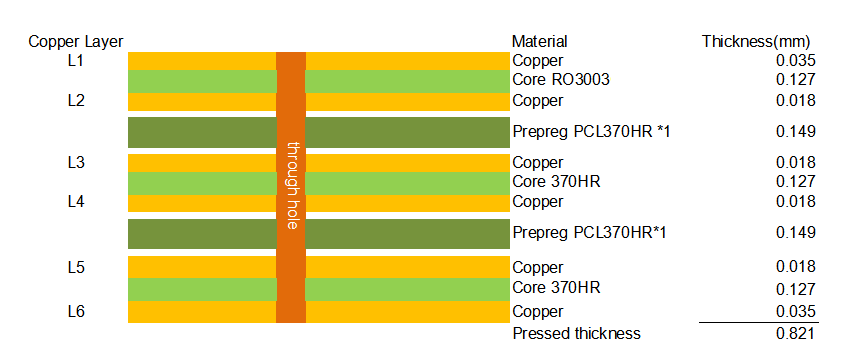
5.PCB Stackup: 6-layer hybrid rigid PCB
6.Type of artwork supplied: Gerber RS-274-X
7.Quality standard: IPC-Class-2
8. Availability: Worldwide
9. Some Typical Applications
- Automotive radar systems
- GPS & satellite antenna hardware
- Cellular communication power amplifiers and antennas
- Wireless communication patch antennas
- Direct broadcast satellite equipment
- Cable system datalink modules
- Remote meter reading devices
- High-speed power backplanes
10. Rogers RO3003 & Isola 370HR Copper Clad Laminate Knowledge
RO3000 series high frequency circuit materials are ceramic-filled PTFE composites designed for commercial microwave and RF applications. The RO3000 family delivers consistent electrical and mechanical stability at competitive pricing. RO3000 laminates maintain stable mechanical properties regardless of dielectric constant selection, enabling reliable multilayer PCB designs combining different dielectric materials without severe warpage or reliability issues. RO3003 is a representative grade within this material series.
10.1 Core Electrical & Material Features
- X and Y axis CTE of RO3003 reaches 17 ppm/°C, closely matched to copper for excellent dimensional stability. Typical etch shrinkage after etching and baking is less than 0.5 mils per inch.
- Z-axis CTE is 24 ppm/°C to guarantee robust plated through-hole reliability under harsh thermal cycling conditions.
- RO3003 has stable dielectric constant across temperature and frequency, suitable for bandpass filters, microstrip patch antennas and voltage-controlled oscillators.
- Low dielectric loss supports operating frequency up to 77 GHz, ideal for stripline and multilayer hybrid PCB constructions.
- RO3003 can be processed with standard PTFE PCB manufacturing techniques with minor process adjustments.
Isola 370HR is a premium lead-free FR-4 laminate and prepreg developed by Polyclad. It adopts patented multifunctional epoxy resin system with Tg 180°C, designed for high-reliability multilayer printed wiring boards. 370HR uses high-quality E-glass fabric to achieve outstanding CAF resistance. This material features low CTE, excellent thermal, chemical and moisture resistance, supports multiple reflow cycles and HDI technology, and is fully RoHS compliant.
10.2 Stackup Design & Rationality Analysis
The 5mil RO3003 high-frequency core paired with 370HR FR4 prepreg brings prominent performance advantages to this 6-layer RO3003 hybrid PCB. RO3003 features low Dk and low Df characteristics to reduce insertion loss during RF and microwave signal transmission. The thin 5mil dielectric layer supports precise impedance control for both differential and single-ended traces. As a high-Tg, heat-resistant prepreg, 370HR delivers strong anti-delamination performance and survives repeated SMT reflow processes. This combination overcomes the thermal instability and high cost of pure ceramic PTFE boards. The hybrid dielectric design balances RF electrical performance and mass-production cost, making it a mainstream stackup solution for small and medium-sized RF modules.
The stackup design targets a finished thickness of 0.82mm for this 6-layer hybrid PCB. The combination of 5mil RO3003 ceramic core and 5mil 370HR prepreg plus copper foils enables precise control of the 0.82mm total thickness and strict thickness tolerance. Design and manufacturing teams must address the CTE discrepancy between RO3003 and 370HR. A segmented heating and cooling lamination profile is required to prevent interlayer delamination. Specialized controls are also implemented to resolve layer shift and board warpage defects common for thin 6-layer hybrid boards.
10.3 Processing & Fabrication Notes
- Hybrid PTFE/FR4 PCB requires customized lamination cycle to relieve thermal stress and minimize board warpage
- Pre-baking of RO3003 and 370HR materials before lamination reduces voiding and delamination risk
- RO3003 requires modified PTFE processing steps, while 370HR follows standard FR4 fabrication workflow
- Copper paste plugging process for 0.15mm vias needs strict parameter validation to ensure hole filling quality
- Blind via fabrication requires accurate depth control for the 1-2 blind via structure
11. Application
RO3003 and 370HR hybrid PCB is widely deployed in automotive radar systems, GPS satellite antenna modules, cellular communication power amplifiers, wireless patch antennas, direct broadcast satellite equipment, cable datalink hardware, remote meter readers and high-speed power backplanes. RO3003 multilayer PCB with RO3003 + 370HR stackup is a preferred hybrid RF board solution for RF engineers seeking stable microwave performance, blind via and copper plugging capability while optimizing total PCB production cost.
12. Product Summary
6-layer Rogers RO3003 PCB is a rigid multilayer RF circuit board built on 5mil RO3003 ceramic-filled PTFE core plus 5mil Isola 370HR FR4 prepreg, with total laminated thickness of 0.82mm. RO3003 hybrid PCB uses 1oz outer copper and 0.5oz inner copper, blue solder mask and white top silkscreen with immersion gold surface finish. The board incorporates 1-2 blind vias and 0.15mm copper paste plugged through holes. This RO3003 PCB undergoes 100% electrical testing before shipment. The mixed stackup of this 6-layer RO3003 PCB balances high-frequency electrical performance, thermal reliability and manufacturing cost, widely adopted for automotive radar, satellite antenna and cellular communication RF systems.
13.DataSheet