


 Home
-
Hybrid PCB
-
RO3003 and Tg170 FR4 Hybrid PCB Rogers 3003 10mil 4-Layer High Frequency PCB for Automotive Radar
Home
-
Hybrid PCB
-
RO3003 and Tg170 FR4 Hybrid PCB Rogers 3003 10mil 4-Layer High Frequency PCB for Automotive Radar
RO3003 and Tg170 FR4 Hybrid PCB Rogers 3003 10mil 4-Layer High Frequency PCB for Automotive Radar
Printed Circuit Boards are custom-made products; the images and specifications provided are for reference only.
1. Product Overview
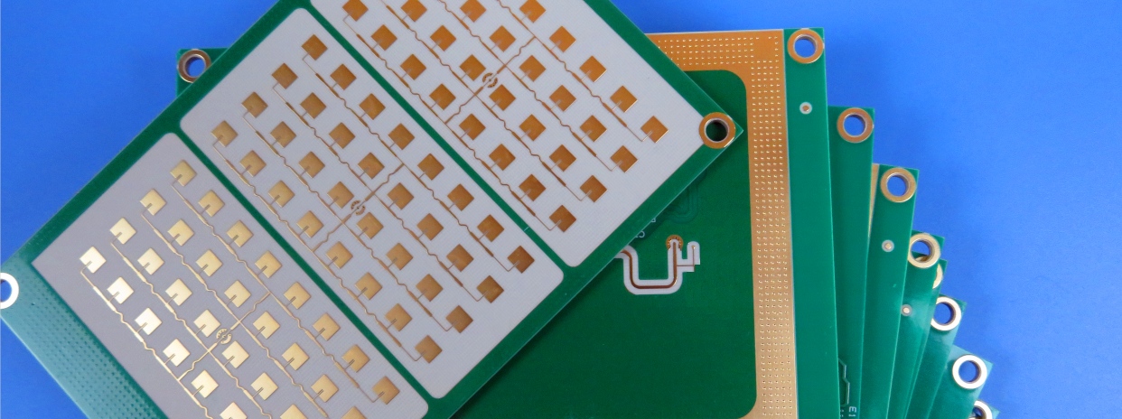
RO3003 Hybrid PCB is a high-performance RF circuit board built with premium 10mil RO3003 high-frequency laminate and Tg170 FR4 substrate. RO3003 4-Layer PCB features 1oz copper thickness on every conductive layer, paired with immersion gold surface treatment, green solder mask coating and white silkscreen marking. The professional configuration of this hybrid PCB delivers superior electrical conductivity, long-term anti-oxidation capability and clear circuit layout identification for high-frequency signal scenarios.
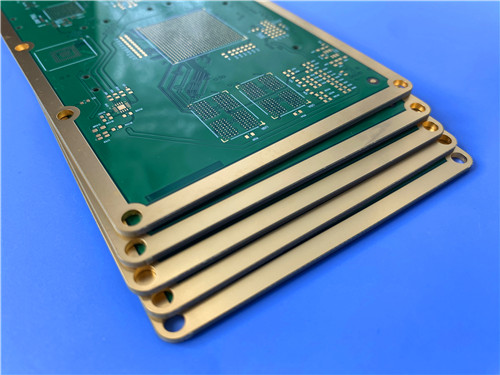
RO3003 FR4 Hybrid PCB features a standard overall pressing thickness of 10miland a board dimension of 127mm × 97mm. Rogers 3003 4-Layer high frequency PCB includes 5 unique design versions with a total production quantity of 5 PCS. Rogers 3003 10mil PCB structure integrates precision controlled depth grooves spanning L2 to L4-Layers, and these groove areas require no electroplating processing, optimizing the manufacturing process while retaining high structural precision of the RF PCB.
RO3003 RF circuit board achieves optimal performance and cost balance via hybrid substrate design. Rogers 3003 dielectric material serves as the core signal transmission medium of this multilayer PCB, providing ultra-low signal loss and stable high-frequency electrical properties. The matched Tg170 FR4 substrate reinforces the mechanical strength and thermal stability of RO3003 PCB, making this hybrid circuit board ideal for commercial microwave equipment and wireless communication electronic devices.
2.PCB Stackup and Specifications
3. PCB Stackup Structure RO3003 4-Layer FR4 Hybrid PCB adopts a symmetrical laminated stackup layout exclusive for high-frequency PCBs. Rogers 3003 multilayer PCB uses a scientific composite structure to evenly disperse internal board stress, eliminate signal distortion, and maintain consistent and reliable high-frequency transmission stability. The detailed stackup configuration of this custom RF PCB is listed below: - Copper_layer_1 – 1 oz 4. Copper Clad Laminate Material Knowledge RO3003 PCB material utilizes RO3000® Series RO3003 high-frequency copper clad laminates, industry-standard ceramic-filled PTFE composite CCL materials dedicated to commercial RF and microwave PCB production. Rogers RO3003 substrate boasts steady electrical parameters and reliable mechanical performance with competitive cost advantages, becoming the mainstream core material for high-precision wireless communication PCB products. 4.1 Basic Material Performance RO3000 series ceramic-filled PTFE laminates maintain consistent mechanical properties across different dielectric constant specifications. This unique trait greatly improves the yield of customized RO3003 FR4 hybrid PCB products, enabling PCB manufacturers to adopt multi-dielectric layer designs without causing board warpage or long-term operational reliability risks for finished PCBs. RO3003 PCB laminate features ultra-stable dimensional stability, with X and Y-axis CTE of 17 ppm/°C that perfectly matches copper foil expansion parameters. The material’s etching shrinkage is controlled below 0.5 mils per inch, and the Z-axis CTE reaches 24 ppm/°C. This property ensures excellent hole wall reliability and structural durability of the RO3003 10mil 4-layer PCB under frequent thermal cycling. Besides, RO3003 substrate maintains fixed dielectric constant under variable temperature and frequency, guaranteeing stable working performance of high-frequency PCBs. 4.2 Processing Characteristics RO3000 series laminates adapt to standard PTFE PCB fabrication processes with only minor parameter adjustments, fully compatible with mainstream PCB production lines. The excellent processability of RO3003 materials supports mass and customized production of immersion gold finished RO3003 PCBs, ensuring unified quality standards for batch RF circuit board products. 4.3 Core Features and Benefits - Low dielectric loss property enables Rogers 3003 PCB to work stably under frequencies up to 77 GHz, fully meeting high-precision signal transmission demands of microwave circuit PCBs. The data in Chart shows the distribution of dissipation factor for RO3003 PCB materials and RO3035 PCB materials. Test Method: IPC-TM-650 2.5.5.5 Condition: 10 GHz 23°C 4.4 Typical Application Fields RO3003 PCB substrate is the core material for high-end RF PCBs, widely applied to automotive radar PCB boards, GPS satellite antenna PCBs, cellular communication power amplifier circuit boards, wireless patch antenna PCBs, direct broadcast satellite equipment circuits, cable system datalink PCBs, remote meter reading circuit boards and power backplane PCBs. 5. Summary Rogers RO3003 and Tg170 FR4 Hybrid PCB is a customized high-performance high-frequency circuit board tailored for RF and microwave industries. RO3003 printed circuit board adopts full 1oz copper layer design and premium immersion gold surface finish, paired with a reliable hybrid stackup structure. The unique L2-L4 controlled depth groove design of this multilayer PCB skips electroplating procedures, simplifying production while ensuring precision. Combining the ultra-low loss high-frequency advantages of RO3003 laminate and the high-temperature resistance of Tg170 FR4 material, this custom PCB delivers balanced performance, stability and cost efficiency, serving as a reliable circuit board solution for microwave communication, RF equipment and automotive radar systems. 6. Datasheet
Item
Parameter
PCB Layer Count
4-Layers
Total Pressing Thickness
0.694mm
Core Material
10mil RO3003 + Tg170 FR-4 Hybrid Material
Copper Foil Weight
1oz Per Layer
Surface Treatment
Immersion Gold
Solder Mask & Silkscreen
Green Solder Mask, White Silkscreen
PCB Dimension
127mm × 97mm
Product Specification
5 Variants, Total 5 PCS
Special Structural Design
Controlled Depth Groove (L2-L4), No Electroplating Required
- RO3003 Core – 10mil
- Prepreg + Tg170 FR-4 Core
- Copper_layer_2 – 1 oz
- Copper_layer_3 – 1 oz
- Prepreg + Tg170 FR-4 Core
- RO3003 Core – 10mil
- Copper_layer_4 – 1 oz 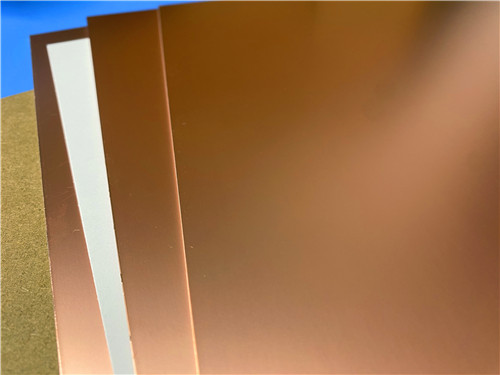
- Temperature-resistant mechanical performance ensures long-term structural stability of stripline circuits and multilayer RO3003 PCB boards in complex working environments.
- High compatibility with epoxy glass materials supports FR4 hybrid lamination, effectively reducing the overall production cost of high-frequency PCBs.
- Low in-plane thermal expansion coefficient enhances SMT assembly accuracy of RO3003 PCBs, suitable for temperature-sensitive precision electronic equipment.
- Mature industrial mass production technology ensures stable quality and cost-effectiveness of commercial RO3003 high frequency PCB products. 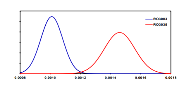
Properties
RO3003 Typical Value
Units
Test Conditions
Test Method
Dielectric Constant (process)
3.00±0.04
-
23˚C, 10 GHz
IPC TM-650 2.5.5.5
Dielectric Constant (design)
3.00
-
8 GHz - 40 GHz
Differential Phase Length
Dissipation Factor
0.0010
-
23˚C, 10 GHz
IPC TM-650 2.5.5.5
Thermal Coefficient of Dielectric Constant
-3
ppm/˚C
-50 to 150˚C, 10 GHz
IPC TM-650 2.5.5.5
Volume Resistivity
107
MΩ-cm
Condition A
IPC TM-650 2.5.17.1
Surface Resistivity
107
MΩ
Condition A
IPC TM-650 2.5.17.1
Decomposition Temperature (Td)
500
˚C TGA
-
ASTM D3850
Coefficient of Thermal Expansion - x
17
ppm/˚C
-55 to 288˚C, 23˚C/50% RH
IPC TM-650 2.4.41
Coefficient of Thermal Expansion - y
16
ppm/˚C
-55 to 288˚C, 23˚C/50% RH
IPC TM-650 2.4.41
Coefficient of Thermal Expansion - z
25
ppm/˚C
-55 to 288˚C, 23˚C/50% RH
IPC TM-650 2.4.41
Thermal Conductivity
0.50
W/(m.K)
50˚C
ASTM D5470
Copper Peel Strength
12.7
lbs/in
1 oz. EDC After Solder Float
IPC TM-650 2.4.8
Young’s Modulus
930, 823
MPa
23˚C
ASTM D638
Dimensional Stability (MD, CMD)
-0.06, 0.07
mm/m
Condition A
IPC TM-650 2.2.4
Flammability
V-0
-
-
UL 94
Moisture Absorption
0.04
%
D48/50
IPC TM-650 2.6.2.1
Density
2.1
g/cm³
23˚C
ASTM D792
Specific Heat Capacity
0.9
J/g/K
-
Calculated
Lead Free Process Compatible
Yes
-
-
-