


 Home
-
Hybrid PCB
-
Hybrid PCB Built on 4mil RO4350B Tg170 FR4 and 8mil RO4003C Laminate for RF Communication & Automotive Radar
Home
-
Hybrid PCB
-
Hybrid PCB Built on 4mil RO4350B Tg170 FR4 and 8mil RO4003C Laminate for RF Communication & Automotive Radar
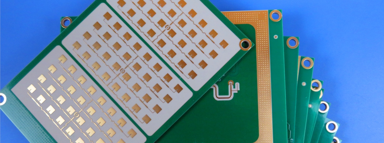
Hybrid PCB Built on 4mil RO4350B Tg170 FR4 and 8mil RO4003C Laminate for RF Communication & Automotive Radar
Printed Circuit Boards are custom-made products; the images and specifications provided are for reference only.
1. Product Overview
RO4350B and RO4003C Hybrid PCB is a high-precision multilayer high frequency circuit board developed for advanced RF and microwave applications. Rogers 8-layer RO4000 series PCB adopts a diversified hybrid substrate stackup, combining 4mil RO4350B laminate, 8mil RO4003C laminate, 4mil RO4450F bondply and Tg170 FR4 dielectric materials to deliver ultra-low signal loss and stable electrical performance across high-frequency working bands.
Rogers 8-Layer Hybrid PCB features differentiated copper thickness design, with 0.5oz copper for inner layers and 1oz copper for outer layers, balancing fine-line circuit conduction and outer-layer current carrying capacity. RO4350B and RO4003C PCB applies professional immersion gold surface finish to enhance surface flatness, oxidation resistance and soldering reliability for precision SMT assembly.
RO4350B and RO4003C high-frequency PCB adopts customized solder mask and silkscreen configuration. The top layer features no solder mask with black silkscreen printing, while the bottom layer adopts blue solder mask without silkscreen marking, meeting diverse circuit identification and insulation protection requirements. The finished pressing thickness of this RO4450F bondply hybrid PCB is 1.054mm, with a standard board dimension of 110mm × 83mm and a single-piece production quantity of 1PCS.
Manufactured in strict accordance with IPC-3 industry standards, this multilayer RO4000 series PCB achieves a 25um hole copper thickness, ensuring stable hole wall conductivity, excellent thermal cycling resistance and long-term operational reliability. The scientific hybrid material matching of this RF PCB effectively optimizes high-frequency transmission performance and structural stability for commercial microwave and wireless communication equipment.

2.PCB Stackup and Specifications
Item |
Parameter |
PCB Layer Count |
8 Layers |
Total Pressing Thickness |
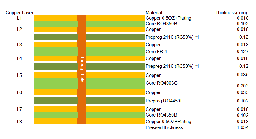
1.054mm |
Hybrid Material Structure |
Top 4mil RO4350B + Middle Tg170 FR-4 + Middle 8mil RO4003C + 4mil RO4450F Bondply + Bottom 4mil RO4350B |
Inner Layer Copper Weight |
0.5oz Per Layer |
Outer Layer Copper Weight |
1oz Per Layer |
Surface Treatment |
Immersion Gold |
Top Layer Solder Mask & Silkscreen |
No Solder Mask, Black Silkscreen |
Bottom Layer Solder Mask & Silkscreen |
Blue Solder Mask, No Silkscreen |
PCB Dimension |
110mm × 83mm |
Production Quantity |
1 PCS |
Hole Copper Thickness |
25um |
Manufacturing Standard |
IPC-3 Standard |
3. PCB Stackup Structure
RO4350B and RO4003C RO4450F Hybrid PCB adopts a customized asymmetrical hybrid stackup structure tailored for multi-material high-frequency PCBs. This 8-layer RO4000 series PCB integrates multiple Rogers high-frequency substrates and Tg170 FR4 reinforcement materials, achieving precise impedance control and ultra-low signal attenuation for high-frequency circuit transmission. The complete stackup configuration of this immersion gold RF PCB is displayed below:
4. Copper Clad Laminate & Bondply Material Knowledge
RO4350B and RO4003C Hybrid PCB adopts classic RO4000 series high-frequency laminates and RO4450F bondply prepregs, which are mainstream ceramic-filled hydrocarbon composite materials for industrial-grade RF PCB manufacturing. This multi-material combination endows the 8-layer PCB with excellent high-frequency stability, mechanical durability and lamination compatibility for multilayer circuit designs.
4.1 RO4000 Series Core Material Overview
RO4000 series laminates including RO4350B and RO4003C are high-performance hydrocarbon ceramic PCB substrates designed for microwave and millimeter-wave frequency applications. Unlike traditional PTFE materials, RO4000 series dielectric materials feature simplified fabrication processes, stable dielectric constant and ultra-low loss tangent across wide temperature and frequency ranges. These materials support high-precision multilayer PCB lamination, effectively avoiding board warpage, delamination and signal distortion during long-term operation of hybrid PCBs.
RO4350B 4mil thin core laminate serves as the top and bottom outer layer substrate of this 8-layer PCB, providing reliable high-frequency signal transmission for outer microwave circuits. RO4003C 8mil thick core material is applied to the middle layer of the hybrid PCB, maintaining stable dielectric parameters and enhancing the overall structural rigidity of the multilayer circuit board. Both materials match perfectly with Tg170 FR4 substrate, realizing cost-effective high-frequency PCB hybrid design.
4.2 RO4350B Material Introduction
RO4350B is a high-performance hydrocarbon ceramic reinforced laminate from the Rogers RO4000 series, featuring rigid thermoset construction that differs from traditional PTFE high-frequency substrates. This RO4350B PCB material delivers premium high-frequency electrical performance while remaining fully compatible with standard FR-4 mass production workflows, enabling this 1.054mm 8-Layerhybrid PCB to achieve outstanding RF performance with controlled manufacturing costs.
This RO4350B substrate maintains ultra-stable electrical characteristics across broad frequency spectrums, especially for circuits operating above 500MHz where ordinary FR4 PCB materials fail to meet low-loss requirements. RO4350B features ultra-low dielectric loss and an extremely low dielectric constant temperature coefficient, delivering flat and consistent Dk performance under fluctuating temperature and frequency conditions. Optional LoPro copper foil further minimizes signal insertion loss, making RO4350B an ideal substrate for broadband microwave and high-frequency RF PCB designs.
RO4350B provides exceptional thermal and dimensional stability for multilayer hybrid PCBs. The material’s CTE closely matches copper foil expansion parameters, ensuring superior dimensional stability during lamination and thermal cycling, which is essential for reliable multi-layer RO4000 PCB construction. Its low Z-axis thermal expansion protects plated through-hole structures from damage under extreme thermal shock. With a Tg higher than 280°C, RO4350B sustains stable expansion behavior throughout all high-temperature PCB fabrication procedures. Unlike PTFE substrates, RO4350B requires no specialized sodium etching for vias, fully supporting automated copper processing and standard mass production equipment.
RO4350B high frequency laminate follows RoHS flame retardant formulations and holds UL 94V-0 safety certification, complying with IPC-4103 industrial standards. The RO4350B PCB material offers strong CAF resistance, tight dielectric tolerance, and repeatable impedance control, supporting precise RF filter and matching network design. Consistent material performance and mature industrial manufacturing enable large-volume production of reliable RO4350B hybrid PCBs with cost-effective pricing.
4.3 RO4350B Application Fields
Thanks to excellent low-loss electrical performance and superior manufacturability, RO4350B high frequency material covers a wide range of commercial and industrial high-frequency electronic applications. RO4350B PCB substrates are widely used in cellular base station antennas and RF power amplifier modules, high-precision RFID tag devices, automotive radar systems and sensitive industrial sensors, as well as low-noise block downconverters for satellite broadcast reception equipment. RO4350B remains the preferred substrate for broadband microwave circuits, precision controlled impedance transmission lines, and custom RF filter PCB structures in modern wireless communication systems.
5.RO4350B Datasheet
| Property | Typical Value | Direction | Units | Condition | Test Method |
| Dielectric Constant εr (Process) | 3.48 ± 0.05 | Z | — | 10 GHz / 23°C | IPC-TM-650 2.5.5.5 Clamped Stripline |
| Dielectric Constant εr (Design) | 3.66 | Z | — | 8 ~ 40 GHz | Differential Phase Length Method |
| Dissipation Factor tanδ | 0.00370.0031 | Z | — | 10 GHz / 23°C2.5 GHz / 23°C | IPC-TM-650 2.5.5.5 |
| Thermal Coefficient of εr | +50 | Z | ppm/°C | -50°C ~ 150°C | IPC-TM-650 2.5.5.5 |
| Volume Resistivity | 1.2 × 10¹⁰ | — | MΩ•cm | COND A | IPC-TM-650 2.5.17.1 |
| Surface Resistivity | 5.7 × 10⁹ | — | MΩ | COND A | IPC-TM-650 2.5.17.1 |
| Electrical Strength | 31.2 (780) | Z | KV/mm (V/mil) | 0.51mm (0.020”) | IPC-TM-650 2.5.6.2 |
| Tensile Modulus | 16,767 (2,432)14,153 (2,053) | XY | MPa (ksi) | Room Temperature | ASTM D638 |
| Tensile Strength | 203 (29.5)130 (18.9) | XY | MPa (ksi) | Room Temperature | ASTM D638 |
| Flexural Strength | 255 (37) | — | MPa (kpsi) | — | IPC-TM-650 2.4.4 |
| Dimensional Stability | <0.5 | X, Y | mm/m (mils/inch) | After etch + E2 / 150°C | IPC-TM-650 2.4.39A |
| Coefficient of Thermal Expansion | 101232 | XYZ | ppm/°C | -55°C ~ 288°C | IPC-TM-650 2.4.41 |
| Tg (Glass Transition Temperature, TMA Method A) | >280 | — | °C | Method A | IPC-TM-650 2.4.24.3 |
| Td (Decomposition Temperature, TGA) | 390 | — | °C | TGA Test | ASTM D3850 |
| Thermal Conductivity | 0.69 | — | W/m·K | 80°C | ASTM C518 |
| Moisture Absorption | 0.06 | — | % | 48 hrs immersion, 0.060” sample, 50°C | ASTM D570 |
| Density | 1.86 | — | g/cm³ | 23°C | ASTM D792 |
| Copper Peel Strength | 0.88 (5.0) | — | N/mm (pli) | After solder float, 1 oz. EDC Foil | IPC-TM-650 2.4.8 |
| Flammability | V-0 | — | — | — | UL 94 |
| Lead-Free Process Compatible | Yes | — | — | — | — |
4.4 RO4400 Series Bondply Family & RO4450F Bondply Characteristics
RO4400 Series bondply is a lineup of high frequency bonding materials tailored for multilayer RF PCB fabrication, fully compatible with RO4000 series laminates including RO4003C and RO4350B used for this 1.054mm 8-Layerhybrid PCB. The series mainly includes RO4450F and RO4460G2 grades, featuring unified high-frequency formula and stable lamination performance for complex multi-layer stackup designs.
High Lamination Adaptability
RO4400 bondply owns high post-cure Tg, supporting sequential multiple lamination cycles for sophisticated multilayer RO4000 PCB structures. It is compatible with standard FR-4 bonding processes, enabling one-time lamination for mixed Rogers and FR4 hybrid stackups. This feature greatly improves production flexibility and structural stability of custom high frequency PCBs.
RO4450F Core Performance Advantages
RO4450F bondply features optimized lateral flow capacity, solving filling difficulties in dense 8-layer PCB stackups. It effectively eliminates internal micro-voids during pressing and ensures compact, uniform lamination structure for this RO4350B and RO4003C hybrid PCB. With stable dielectric parameters, RO4450F maintains ultra-low signal loss at high frequency bands without interfering RF signal transmission.
RO4460G2 Supplementary Features
As another premium grade of RO4400 family, RO4460G2 provides stable 6.15 Dk dielectric control and low Z-axis thermal expansion. Both RO4450F and RO4460G2 deliver reliable plated through-hole performance under thermal cycling conditions. All RO4400 bondply materials meet UL 94 V-0 flame retardant standard and support lead-free soldering processes.
Stable Mechanical & Electrical Properties
RO4450F bondply achieves a stable Dk of 3.52±0.05 and low loss tangent of 0.0040 at 10GHz. Its Z-axis CTE ranges from 43 to 60 ppm/°C, offering excellent CAF resistance and anti-delamination capability. These properties guarantee long-term structural reliability for the 1.054mm 8-layer RO4000 hybrid PCB in high-temperature working environments.
FR4 Hybrid Compatibility
RO4450F bondply matches standard FR-4 bonding temperature perfectly. It enables integrated pressing of RO4000 high-frequency substrates and Tg170 FR4 reinforcement layers, simplifying the manufacturing flow of multilayer hybrid PCBs while maintaining high production yield and consistent board quality.
4.5 Tg170 FR4 Auxiliary Material Advantages
Tg170 high-Tg FR4 substrate is used as the intermediate reinforcing layer of this RO4000 series hybrid PCB. It provides excellent mechanical support and thermal resistance, making up for the insufficient structural toughness of single high-frequency ceramic materials. The high glass transition temperature of Tg170 FR4 enables the 8-layer PCB to withstand multiple high-temperature reflow processes without deformation, improving the overall structural reliability of the multilayer circuit board while reducing comprehensive production costs.
4.6 Core Application Fields
This RO4350B RO4003C RO4450F hybrid 8-layer PCB and RO4400 series bondply high frequency PCBs are widely applied in professional radio frequency and microwave fields. Typical application scenarios include backhaul radios, industrial communication systems, RF power amplifiers, small cell base stations and DAS distributed antenna systems. The stable electrical performance and reliable multilayer structure make this 1.054mm 8-LayerRO4000 Hybrid PCB a core circuit board solution for high-precision wireless communication and microwave radar equipment.
5. Summary
RO4350B RO4003C RO4450F and FR4 Hybrid PCB is a high-standard multilayer high-frequency circuit board compliant with IPC-3 manufacturing specifications. 8-layer RO4000 series Hybrid PCB adopts differentiated inner and outer copper thickness design, paired with premium immersion gold surface finish and personalized solder mask silkscreen configuration. The multi-material hybrid stackup composed of RO4350B, RO4003C, RO4450F bondply and Tg170 FR4 balances ultra-low high-frequency signal loss, excellent structural stability and industrial manufacturability. The 25um standard hole copper thickness guarantees reliable hole conduction performance, making this custom RF PCB suitable for high-precision microwave and radio frequency communication equipment with stable and long-lasting operating performance.
6. RO4450F Bondply Datasheet
| Properties | RO4450F | Direction | Units | Test Conditions | Test Method |
| Dielectric Constant | 3.52 ± 0.05 | Z | - | 23˚C @ 50% RH, 10 GHz | IPC TM-650 2.5.5.5 |
| Dissipation Factor | 0.004 | Z | - | 23˚C @ 50% RH, 10 GHz | IPC TM-650 2.5.5.5 |
| Volume Resistivity | 8.93 X10⁸ | - | Mohm-cm | C-96/35/90 | IPC TM-650 2.5.17.1 |
| Surface Resistivity | 1.03 X10⁷ | X,Y | Mohm | C-96/35/90 | IPC TM-650 2.5.17.1 |
| Electrical Strength (dielectric strength) | 1000 | Z | V/mil | D-48/50 | IPC TM-650 2.5.6.2 |
| Decomposition Temperature (Td) | 390 | - | ˚C | 2hrs @ 105˚C, 5% Weight Loss | IPC TM-650 2.3.40 |
| Glass Transition (Tg) | >280 | - | ˚C TMA | A | IPC-TM-650 2.4.24.5 |
| Coefficient of Thermal Expansion | 19 | X | ppm/˚C | -55˚C to 288˚C | IPC TM-650 2.4.41 |
| Coefficient of Thermal Expansion | 17 | Y | ppm/˚C | -55˚C to 288˚C | IPC TM-650 2.4.41 |
| Coefficient of Thermal Expansion | 50 | Z | ppm/˚C | -55˚C to 288˚C | IPC TM-650 2.4.41 |
| Thermal Conductivity | 0.65 | Z | W/(m.K) | 80˚C, z direction | ASTM D5470 |
| Copper Peel Strength after Thermal Stress | 0.70 (4.0) | Z | N/mm (lbs/in) | 10s @288˚C, 35 μm foil | IPC TM-650 2.4.8 |
| Glass | 1080 | - | - | - | - |
| Resin-Content | 80 | - | - | - | - |
| Color | White | - | - | - | - |
| Flammability | V-0 | - | - | C48/23/50 & C168/70 | UL 94 |
| Moisture Absorption | 0.04 | - | % | D24/23 | IPC TM-650 2.6.2.1 |
| Lead Free Process Compatible | Yes | - | - | - | - |