



 Home
-
High frequency PCB
-
TMM10i 2-Layer Rigid PCB 75mil Rogers TMM10i RF Laminate with 1OZ Copper, ENIG Surface Finish and No Solder Mask
TMM10i 2-Layer Rigid PCB 75mil Rogers TMM10i RF Laminate with 1OZ Copper, ENIG Surface Finish and No Solder Mask
Printed Circuit Boards are custom-made products; the images and specifications provided are for reference only.
1. Introduction
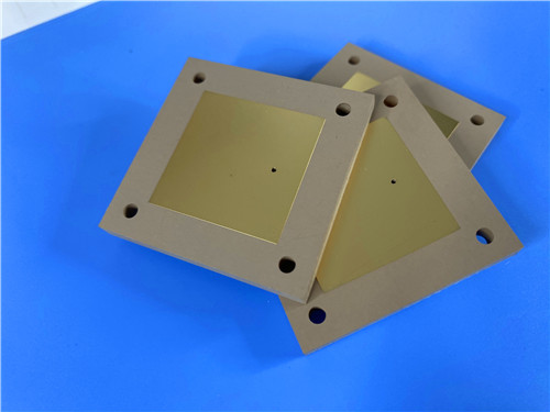
TMM10i 2-layer PCB is a rigid printed circuit board built on 75mil (1.905 mm) Rogers TMM10i high-frequency circuit laminates. TMM10i ceramic thermoset polymer composite circuit board delivers outstanding isotropic dielectric performance, copper-matched thermal expansion and reliable plated through-hole performance for stripline and microstrip RF designs. TMM10i printed circuit board integrates the advantages of ceramic and PTFE substrates while supporting simplified PCB fabrication workflows.
2. Features
- 2-layer rigid PCB built on Rogers TMM10i laminate, board dimension 87.05 mm x 46.3 mm=1PCS, +/- 0.15mm
- 75mil (1.905mm) core substrate, finished board thickness of 2 mm, 1oz (1.4 mils) outer copper weight
- Minimum Trace/Space: 5/6 mils; Minimum Hole Size: 0.4mm, no blind vias
- Via plating thickness: 20 μm; immersion gold surface finish
- No top and bottom silkscreen, no top and bottom solder mask
- Dk of 9.80 +/- 0.245, dissipation factor of 0.0020 at 10GHz
- Low thermal coefficient of Dk of -43 ppm/°K, X/Y/Z CTE: 19ppm/K, 19ppm/K,20ppm/K
- Thermal Conductivity of 0.76W/mk, decomposition temperature Td up to 425 °C
- 100% Electrical test used prior to shipment, available for worldwide supply
3. Benefits
- Isotropic material properties eliminate performance deviation from anisotropic glass reinforced substrates
- Copper-matched thermal expansion ensures excellent dimensional stability and reliable plated through holes
- Strong resistance to creep and cold flow, stable structure under long term thermal and mechanical load
- Good resistance to fabrication chemicals to reduce substrate damage during PCB manufacturing
- No sodium napthanate pre-treatment required before electroless plating to streamline production
- Thermoset resin construction enables stable, high-reliability wire bonding for high-frequency assemblies
4. PCB Construction Details
| Parameter | Specification |
| Base material | TMM10i |
| Layer count | Double sided |
| Board dimensions | 87.05 mm x 46.3 mm=1PCS, +/- 0.15mm |
| Minimum Trace/Space | 5/6 mils |
| Minimum Hole Size | 0.4mm |
| Blind vias | No |
| Finished board thickness | 2 mm |
| Finished Cu weight | 1oz (1.4 mils) outer layers |
| Via plating thickness | 20 μm |
| Surface finish | Immersion gold |
| Top Silkscreen | No |
| Bottom Silkscreen | No |
| Top Solder Mask | No |
| Bottom Solder Mask | No |
| Pre-shipment Test | 100% Electrical test used prior to shipment |
5. PCB Stackup
- Copper_layer_1 - 35 μm
- Rogers TMM10i Core - 1.905 mm (75mil)
- Copper_layer_2 - 35 μm
6. PCB Statistics
- Components: 48
- Total Pads: 62
- Thru Hole Pads: 43
- Top SMT Pads: 19
- Bottom SMT Pads: 0
- Vias: 39
- Nets: 2
7. Type of artwork supplied
Gerber RS-274-X
8. Quality standard
IPC-Class-2
9. Availability
worldwide
10. Rogers TMM Series Copper Clad Laminate (CCL) Introduction: TMM10i
10.1 TMM10i Laminates Product Introduction
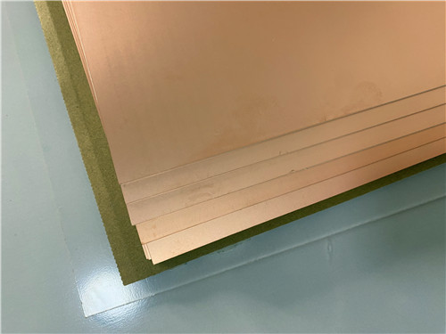
- TMM10i isotropic thermoset microwave material is a ceramic thermoset polymer composite developed for high plated thru-hole reliability stripline and microstrip applications.
- TMM10i PCB material maintains isotropic dielectric constant. Like other TMM series materials, TMM10i combines favorable properties of ceramic and PTFE substrates while supporting simple processing similar to soft substrate techniques.
- Rogers TMM10i belongs to premium TMM series thermoset microwave materials. These ceramic-hydrocarbon-polymer composite laminates merge strengths from traditional ceramic substrates and PTFE microwave laminates.
- TMM10i PCB laminate overcomes processing limits of ceramic materials and thermal instability issues of PTFE materials. It provides consistent isotropic performance, great process adaptability and stable structure, serving as a cost-effective alternative to high-priced alumina substrates in high-frequency microwave industries.
10.2 Unique Isotropic Material Design
- TMM10i high frequency laminate delivers fully isotropic dielectric and mechanical characteristics. Dielectric constant and thermal expansion stay consistent across all directions.
- This property avoids circuit performance shifts triggered by material anisotropy commonly found in glass-reinforced substrates.
- Ultra-stable Dk value and low thermal coefficient of dielectric constant at -43 ppm/°K maintain steady frequency and phase performance under variable temperature conditions, suitable for temperature-sensitive precision microwave circuits.
10.3 Advanced Thermoset Resin Structural Advantages
- Unlike thermoplastic PTFE materials, TMM10i uses high-performance thermoset resin formulation and will not soften or deform under continuous high-temperature operation.
- This property supports safe and reliable wire bonding without pad warping, pad lifting or substrate damage.
- High mechanical rigidity with strong anti-creep and anti-cold-flow capability preserves stable dimensional performance under sustained mechanical and thermal loading.
10.4 Simplified Processing & Chemical Stability
- TMM10i laminates show excellent resistance to common PCB process chemicals including etching solutions and organic solvents, lowering substrate damage and yield loss in fabrication.
- TMM10i circuit material removes the requirement for complex sodium napthanate surface treatment before electroless plating. It shortens manufacturing cycles and cuts total production costs.
- TMM10i is fully compatible with all standard conventional printed circuit board processing techniques.
10.5 Thermal & Structural Reliability Mechanism
- X/Y/Z three-axis thermal expansion coefficients of TMM10i closely match copper foil. It delivers low etching shrinkage and dependable plated through-hole performance even under severe thermal cycling.
- Thermal conductivity reaches 0.76W/mk, nearly double that of conventional PTFE-ceramic composite substrates, to dissipate heat efficiently for high-power RF circuits and prevent thermal accumulation related performance drop.
- High decomposition temperature of 425°C supports high-temperature processing and long-duration high-power operating scenarios.
10.6 Product Customization & Versatility
- Rogers TMM10i can be manufactured in a broad thickness range from 0.0015 inches to 0.500 inches, and clad with 0.5oz to 2oz electrodeposited copper foil.
- TMM10i laminate can be directly bonded with brass or aluminum base plates for high-power heat dissipation structural designs.
- Versatile performance and process compatibility allow TMM10i to replace conventional alumina ceramic substrates, delivering premium microwave performance with improved processability and better cost efficiency.
11. Some Typical Applications
- RF and microwave circuitry
- Power amplifiers and combiners
- Filters and couplers
- Satellite communication systems
- Global Positioning Systems Antennas
- Patch Antennas
- Dielectric polarizers and lenses
- Chip testers
12. Product Summary
TMM10i 2-Layer high-frequency PCB is a 2mm printed circuit board built on 75mil TMM10i high-frequency circuit laminates. TMM10i RF circuit board features isotropic ceramic thermoset composite substrate, immersion gold surface finish and no solder mask or silkscreen. TMM10i PCB laminate offers copper matched CTE, high thermal conductivity and reliable wire bonding capability, ideal for satellite communication systems, GPS antennas, microwave filters and power amplifier projects. Manufactured per IPC-Class-2 standards, this microwave material accepts global orders.
13.TMM10i DataSheet
| Properties | Typical Value | Direction | Units | Conditions | Test Method |
| ELECTRICAL PROPERTIES | |||||
| Dielectric Constant (process) | 9.80 ± 0.245 | Z | — | 10 GHz | IPC-TM-650 2.5.5.5 |
| Dielectric Constant (design) | 9.9 | — | — | 8 GHz – 40 GHz | Differential Phase Length Method |
| Dissipation Factor (process) | 0.0020 | Z | — | 10 GHz | IPC-TM-650 2.5.5.5 |
| Thermal Coefficient of Dielectric Constant | -43 | — | ppm/°K | -55°C ~ +125°C | IPC-TM-650 2.5.5.5 |
| Insulation Resistance | >2000 | — | Gohm | C/96/60/95 | ASTM D257 |
| Volume Resistivity | 2×10⁸ | — | MΩ·cm | — | ASTM D257 |
| Surface Resistivity | 4×10⁷ | — | MΩ | — | ASTM D257 |
| Dielectric Strength | 267 | Z | V/mil | — | IPC-TM-650 2.5.6.2 |
| THERMAL PROPERTIES | |||||
| Decomposition Temperature (Td, TGA) | 425 | — | °C | — | ASTM D3850 |
| CTE X-axis (0–140°C) | 19 | X | ppm/K | 0°C ~ 140°C | ASTM E 831 / IPC-TM-650 2.4.41 |
| CTE Y-axis (0–140°C) | 19 | Y | ppm/K | 0°C ~ 140°C | ASTM E 831 / IPC-TM-650 2.4.41 |
| CTE Z-axis (0–140°C) | 20 | Z | ppm/K | 0°C ~ 140°C | ASTM E 831 / IPC-TM-650 2.4.41 |
| Thermal Conductivity | 0.76 | Z | W/m/K | 80°C | ASTM C518 |
| MECHANICAL PROPERTIES | |||||
| Copper Peel Strength (after solder float, 1 oz. EDC) | 5.0 (0.9) | X,Y | lb/inch (N/mm) | After solder float | IPC-TM-650 2.4.8 |
| Flexural Strength (MD/CMD) | — | X,Y | kpsi | Condition A | ASTM D790 |
| Flexural Modulus (MD/CMD) | 1.80 | X,Y | Mpsi | Condition A | ASTM D790 |
| PHYSICAL PROPERTIES | |||||
| Water Absorption (1.27mm / 0.050” sample) | 0.16 | — | % | D/24/23 | ASTM D570 |
| Water Absorption (3.18mm / 0.125” sample) | 0.13 | — | % | D/24/23 | ASTM D570 |
| Specific Gravity | 2.77 | — | — | Condition A | ASTM D792 |
| Specific Heat Capacity | 0.72 | — | J/g/K | Condition A | Calculated |
| Lead-Free Process Compatible | YES | — | — | — | — |