


 Home
-
F4B PCB
-
F4BTMS233 2-Layer Immersion Gold PCB 3.5mil Laminate PCB with Dk 2.33 for Aerospace and Radar
F4BTMS233 2-Layer Immersion Gold PCB 3.5mil Laminate PCB with Dk 2.33 for Aerospace and Radar
Printed Circuit Boards are custom-made products; the images and specifications provided are for reference only.
1. Product Introduction
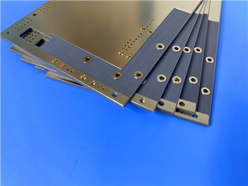
F4BTMS233 2-Layer high-frequency rigid PCB is an aerospace-grade microwave printed circuit board built for high-performance RF and satellite communication systems. This 1.1mm thick circuit board uses F4BTMS233 PTFE ultra-thin ultra-fine fiberglass cloth ceramic-filled substrate as its core PCB substrate. The upgraded F4BTMS series minimizes fiberglass interference on electromagnetic transmission, with low dielectric loss and outstanding dimensional stability. Finished with ENIG surface treatment and manufactured to IPC-Class-2 standards, this PCB delivers consistent electrical performance for radar, phased array antenna and aerospace electronic hardware.
2. Core Product Features
- Dk of 2.33 at 10GHz; dissipation factor of 0.0010 at 10GHz and 0.0011 at 20GHz for low signal attenuation
- X/Y/Z CTE: 35 / 40 / 220 ppm/°C (-55°C ~ 288°C); low Dk thermal coefficient of -122 ppm/°C (-55°C ~150°C)
- UL-94 V0 flammability rating and ultra-low moisture absorption of 0.02%
- Standard RTF low roughness copper foil reduces conductor loss while maintaining strong peel strength
- Precision fabrication with 5/8 mils minimum trace/space and 0.4mm minimum hole size for fine-line microwave circuit board production
- Blind-via-free rigid stackup, compatible with standard PTFE fabrication processes and dense hole machining
3. Product Performance Benefits
- Tight Dk tolerance and reliable batch consistency, supporting phase-sensitive antenna designs
- Stable dielectric properties up to 40GHz, preserving phase stability across wide temperature ranges from -55℃ to 150℃
- Good radiation resistance and low outgassing, fully satisfying aerospace vacuum application requirements
- Balanced thermal conductivity and low thermal expansion, boosting plated through-hole reliability under thermal cycling
- Supports multi-layer and backplane fabrication, works well with copper or aluminum base structures
4. PCB Construction Details
| Parameter Item | Technical Specification |
| Board Dimensions | 49mm x 78.6mm (1PCS), Tolerance: +/- 0.15mm |
| Minimum Trace/Space | 5/8 mils |
| Minimum Hole Size | 0.4mm |
| Blind Vias Design | No Blind Vias |
| Finished Board Thickness | 1.1mm |
| Finished Copper Weight (Outer Layers) | 1oz (1.4 mils) outer layers |
| Via Plating Thickness | 20 μm |
| Surface Finish | ENIG |
| Top Silkscreen | White |
| Bottom Silkscreen | No |
| Top Solder Mask | Black |
| Bottom Solder Mask | No |
| Pre-Shipment Testing | 100% Electrical test prior to shipment |
5. PCB Stackup Structure
F4BTMS233 2-Layer rigid printed circuit board adopts a simple symmetrical stackup optimized for F4BTMS233 high-frequency laminate, maintaining clean signal transmission for microwave and RF applications:
- Copper_layer_1: 35 μm
- F4BTMS233 Core: 0.09 mm (3.5mil)
- Copper_layer_2: 35 μm
6. PCB Statistical Parameters
This compact circuit layout accommodates lightweight component assembly for aerospace microwave hardware:
- Components: 26
- Total Pads: 49
- Thru Hole Pads: 31
- Top SMT Pads: 18
- Bottom SMT Pads: 0
- Vias: 34
- Nets: 2
7. Artwork Supplied Type
Standard Gerber RS-274-X format artwork is provided, compatible with global manufacturing equipment for ceramic-filled PTFE high-frequency laminates and precision microwave PCB production.
8. Quality Manufacturing Standard
F4BTMS233 PCB laminate and finished printed circuit board is manufactured in compliance with IPC-Class-2 industrial standards, ensuring stable mechanical and electrical performance for high-frequency circuit materials.
9. Product Availability
F4BTMS233 2-Layer high-frequency PCB is available for worldwide supply, supporting global customized processing and bulk procurement.
10. Typical Application Scenarios
With low dielectric loss and aerospace qualified material properties, F4BTMS233 RF circuit board is widely deployed in high-end wireless and space electronic systems:
- Aerospace equipment, space and cabin equipment
- Microwave, RF systems
- Radar, military radar
- Feed networks
- Phase-sensitive antennas, phased array antennas
- Satellite communications
11. F4BTMS Copper Clad Laminate (CCL) Knowledge
F4BTMS series PTFE ultra-fine fiberglass cloth ceramic-filled substrates are upgraded materials derived from the F4BTM series. Optimized material formulation and manufacturing processes deliver enhanced performance and a broader Dk selection range. The material is aerospace-grade high reliability and serves as a direct alternative to equivalent foreign substrates.
 F4BTMS233.jpg)
11.1 Core Material Advantages
- Minimized Fiberglass Effect: Reinforced with a small quantity of ultra-thin ultra-fine fiberglass cloth and blended with evenly distributed nano-ceramics in PTFE resin. The design reduces anisotropy, dielectric loss and negative influence on electromagnetic wave propagation.
- Superior Physical & Electrical Performance: Improved dielectric strength, thermal conductivity and low thermal expansion. It maintains stable dielectric temperature characteristics for high-frequency circuits.
- RTF Copper Foil as Standard: RTF low roughness copper foil lowers conductor loss with reliable peel strength. It can be matched with copper or aluminum bases and supports multi-layer, backplane, fine line and dense hole processing.
11.2 Key Features and Corresponding Performance Benefits
- Ultra-Low Dielectric Loss: Consistent low loss up to 40GHz, meeting strict phase-sensitive application requirements.
- Wide-Range Thermal Stability: Stable Dk and loss from -55℃ to 150℃, excellent radiation resistance and low vacuum outgassing for aerospace use.
- Controlled Thermal Expansion: Optimized X/Y/Z CTE improves dimensional stability and copper barrel reliability during temperature cycling.
- Enhanced Thermal Conductivity: Handles higher power operation while retaining low water absorption.
11.3 Extended Application Scenarios of F4BTMS Laminate PCB
- Space cabin and aviation aerospace modules
- Military radar and microwave feed network assemblies
- Phased array and phase-sensitive antenna substrates
- Satellite communication RF circuit boards
12. Product Summary
3.5mil F4BTMS233 laminate PCB is an aerospace-grade low-loss microwave printed circuit board. This 1.1mm thick board uses ENIG surface finish and F4BTMS233 ceramic-filled PTFE laminate as its core dielectric. F4BTMS233 high frequency laminate features Dk 2.33 at 10GHz, ultra-low dissipation factor, low outgassing and strong radiation resistance. Compliant with IPC-Class-2 standards, F4BTMS233 PCB substrate fits satellite communication, phased array antenna, military radar and high-power RF systems.
13. F4BTMS233 DataSheet
| Properties | Test Conditions | Unit | Typical Value |
| Dielectric Constant (typical) | 10 GHz | - | 2.33 |
| Dielectric Constant Tolerance | - | - | ±0.03 |
| Dielectric Constant (design) | 10 GHz | - | 2.33 |
| Dissipation Factor (typical) | 10 GHz | - | 0.0010 |
| Dissipation Factor (typical) | 20 GHz | - | 0.0011 |
| Dissipation Factor (typical) | 40 GHz | - | 0.0015 |
| Thermal Coefficient of Dielectric Constant | -55 to 150˚C | ppm/˚C | -122 |
| Copper Peel Strength | 1 OZ RTF copper foil | N/mm | >2.4 |
| Volume Resistivity | Ambient condition | MΩ.cm | ≥1×10⁸ |
| Surface Resistivity | Ambient condition | MΩ | ≥1×10⁸ |
| Electric Strength (Z direction) | 5KW, 500V/s | KV/mm | >30 |
| Dielectric Breakdown Voltage (XY direction) | 5KW, 500V/s | KV | >38 |
| Coefficient of Thermal Expansion (X,Y direction) | -55 to 288˚C | ppm/˚C | 35-40 |
| Coefficient of Thermal Expansion (Z direction) | -55 to 288˚C | ppm/˚C | 220 |
| Thermal Stress | 260˚C, 10s, 3 cycles | - | No delamination |
| Moisture Absorption | 20±2˚C, 24 hours | % | 0.02 |
| Density | Ambient temperature | g/cm3 | 2.22 |
| Continuous Operating Temperature | Thermal chamber | ℃ | -55~+260 |
| Thermal Conductivity | Z direction | W/(M.K) | 0.28 |
| Flammability | - | UL-94 | V-0 |
| Material Composition | - | - | PTFE, ultra-thin and ultra-fine quartz glass fiber |