


 Home
-
F4B PCB
-
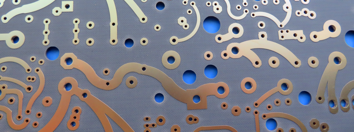
F4BME245 Double-Sided Rigid PCB Wangling 4mil F4BME245 Immersion Gold PCB for RF and Microwave
F4BME245 Double-Sided Rigid PCB Wangling 4mil F4BME245 Immersion Gold PCB for RF and Microwave
Printed Circuit Boards are custom-made products; the images and specifications provided are for reference only.
Introduction
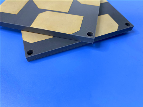
F4BME245 PCB is a 2-layer rigid printed circuit board built on Wangling F4BME245 high-frequency laminates. F4BME245 PCB substrate adopts PTFE fiberglass cloth copper-clad laminate and reverse-treated foil copper cladding, delivering outstanding low PIM performance for RF and microwave circuit designs. F4BME245 PCB material provides stable electrical characteristics, fine line capability and minimized conductor loss, making it well suited for high-precision radio frequency circuit development.
2. Features
- Constructed from Wangling F4BME245 PTFE composite PCB laminate with RTF copper foil for low PIM performance
- Finished board thickness of 0.2 mm, minimum trace/space at 4/7 mils and minimum hole size of 0.5 mm
- Immersion gold surface finish, no solder mask and no silkscreen on both top and bottom sides
- 1 oz outer copper weight with 20 μm via plating thickness, fully compliant with IPC-Class-2 quality standard
- Tunable dielectric constant by adjusting PTFE and fiberglass ratio, balancing low dielectric loss and dimensional stability
- Full 100% electrical test performed before shipment, available for global delivery
3. Benefits
- The F4BME245 high-frequency laminate achieves better electrical stability and lower dielectric loss than traditional F4B245 material, serving as a cost-effective alternative to imported microwave material
- RTF copper cladding supports precise fine-line etching and reduces conductor loss, meeting strict requirements of high-precision RF circuit boards
- Adjustable fiberglass content optimizes thermal expansion and temperature drift, ensuring consistent performance under changing working conditions
- IPC-Class-2 quality control and pre-shipment electrical testing lower failure risk for microwave and communication circuits
- Worldwide availability supports small batch and mass production for satellite, radar and antenna projects
4. PCB Construction Details
| Parameter | Specification |
| Board dimensions | 85.6 mm x 47 mm=1PCS, +/- 0.15mm |
| Minimum Trace/Space | 4/7 mils |
| Minimum Hole Size | 0.5mm |
| Finished board thickness | 0.2mm |
| Finished Cu weight | 1oz (1.4 mils) outer layers |
| Via plating thickness | 20 μm |
| Surface finish | Immersion gold |
| Top Silkscreen | No |
| Bottom Silkscreen | No |
| Top Solder Mask | No |
| Bottom Solder Mask | No |
| Pre-shipment Test | 100% Electrical test used prior to shipment |
5. PCB Stackup
- Copper_layer_1 - 35 μm
- F4BME245 Core - 0.102 mm (4mil)
- Copper_layer_2 - 35 μm
6. PCB Statistics
- Components: 50
- Total Pads: 39
- Thru Hole Pads: 21
- Top SMT Pads: 18
- Bottom SMT Pads: 0
- Vias: 34
- Nets: 9
7. Type of artwork supplied
Gerber RS-274-X
8. Quality standard
IPC-Class-2
9. Availability
Worldwide
10. PTFE Fiberglass Cloth Copper-Clad Laminate (CCL) Knowledge: F4BM, F4BME and F4BME245
10.1 Product Introduction
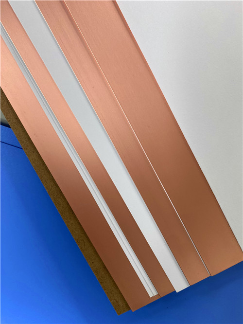
- This series of PTFE fiberglass cloth copper-clad laminate is manufactured from fiberglass cloth, PTFE resin, and PTFE film through scientific formulation and strict compression processes.
- Compared with standard F4B laminate, it delivers upgraded electrical performance, featuring a wider range of optional dielectric constants, low dielectric loss, higher insulation resistance and more stable performance. It can act as a viable replacement for equivalent foreign laminate products.
- F4BM and F4BME share the same dielectric core but adopt different copper foils. F4BM uses ED copper foil and suits applications without PIM requirements. F4BME uses reverse-treated RTF copper foil to achieve excellent PIM performance, tighter line control and reduced conductor loss.
- F4BM and F4BME support adjustable dielectric constants by tuning the proportion of PTFE and fiberglass cloth to balance low loss and improved dimensional stability. A higher fiberglass ratio brings higher dielectric constant, better dimensional stability, lower thermal expansion coefficient and improved temperature drift performance with a slight rise in dielectric loss.
10.2 Product Features
- DK 2.17–3.0 available, DK customizable
- Low dielectric loss
- F4BME paired with RTF copper foil for excellent PIM performance
- Multiple available sizes, cost-saving
- Radiation resistant, low outgassing
- Mature commercialized material, suitable for high-volume production and cost-effective
10.3 Typical Applications
- Microwave, RF, and radar
- Phase shifters, passive components
- Power dividers, couplers, combiners
- Feed networks, phased array antennas
- Satellite communications, base station antennas
12.Product Summary
F4BME245 high-frequency rigid PCB delivers reliable RF performance for microwave and communication applications. This printed circuit board uses F4BME245 PTFE copper clad laminate with immersion gold surface finish and ultra-thin 0.2mm finished thickness. F4BME245 high-frequency circuit laminates support fine trace designs and low PIM operation, widely adopted for phased array antennas, radar systems and satellite communication hardware. The product follows IPC-Class-2 standards and offers global supply.
13.F4BME245 DataSheet
| Product Model / Data | Product Characteristic | Test Condition | Unit | Value |
| F4BME245 | Typical Dielectric Constant | 10GHz | / | 2.45 |
| F4BME245 | Dielectric Constant Tolerance | / | / | ±0.05 |
| F4BME245 | Typical Dissipation Factor | 10GHz | / | 0.0012 |
| F4BME245 | Typical Dissipation Factor | 20GHz | / | 0.0017 |
| F4BME245 | Temperature Coefficient of Dielectric Constant | -55oC~150oC | PPM/℃ | -120 |
| F4BME245 | Peel Strength | 1 OZ F4BM | N/mm | >1.8 |
| F4BME245 | Peel Strength | 1 OZ F4BME | N/mm | >1.6 |
| F4BME245 | Volume Resistivity | Normal Condition | MΩ.cm | ≥6×10⁶ |
| F4BME245 | Surface Resistance | Normal Condition | MΩ | ≥1×10⁶ |
| F4BME245 | Electric Strength (Z Direction) | 5KW,500V/s | KV/mm | >25 |
| F4BME245 | Breakdown Voltage (XY Direction) | 5KW,500V/s | KV | >32 |
| F4BME245 | Coefficient of Thermal Expansion XY Direction | -55 o~288oC | ppm/oC | 20-25 |
| F4BME245 | Coefficient of Thermal Expansion Z Direction | -55 o~288oC | ppm/oC | 187 |
| F4BME245 | Thermal Stress | 260℃,10s,3 times | / | No Delamination |
| F4BME245 | Water Absorption | 20±2℃,24h | % | ≤0.08 |
| F4BME245 | Density | Room Temperature | g/cm3 | 2.22 |
| F4BME245 | Long Term Operating Temperature | Temperature Chamber | ℃ | -55~+260 |
| F4BME245 | Thermal Conductivity Z Direction | / | W/(M.K) | 0.30 |
| F4BME245 | PIM Value | Only for F4BME | dBc | ≤-159 |
| F4BME245 | Flammability | / | UL-94 | V-0 |
| F4BME245 | Material Composition | / | / | PTFE, Fiberglass Cloth |
| Note | F4BM matched with ED copper foil, F4BME matched with reverse RTF copper foil | / | / | / |