.png)
F4BME245 PCB Substrates Introduction Wangling F4BME245 is a reinforced laminate belonging to the F4BME product series, crafted with a balanced material composition and stringent, consistent process control. Built on a foundation of fiberglass cloth integrated with high-quality PTFE resin and films, F4BME245 high frequency laminate delivers enhanced electrical stability compared to traditional F4B materials. This high-frequency laminate boasts controlled dielectric properties, low signal loss, and reliable long-term performance, positioning it as a practical domestic alternative for RF, microwave, and select aerospace applications. To optimize performance, F4BME245 laminate utilizes reverse-treated foil (RTF) copper, which supports reduced conductor loss and superior impedance control. This makes it an ideal choice for telecommunications and RF designs where passive intermodulation (PIM) performance is a critical requirement. Its carefully engineered material composition ensures stable electrical behavior across fluctuating temperature ranges while maintaining robust mechanical properties for end-to-end reliability. F4BME245 PCB substrate is widely applied in high-demand areas such as phased array antennas, automotive radar systems, and satellite communication equipment—all of which require consistent performance and seamless process compatibility. As a functional, adaptable PCB material, F4BME245 copper clad laminates meets the rigorous needs of modern RF and wireless applications without overstating capabilities, striking a balance between performance and practicality for industrial use cases. Features & Benefits -Low DK -Low loss -F4BME paired with RTF copper foil, excellent PIM performance -Diverse sizes, cost-effective -Radiation resistance, low outgassing -Commercialized, large-scale production, high cost-effectiveness Laminate Models and Data Sheet The data sheet provides technical parameters and specifications for a specific product model. It includes various characteristics and performance measurements of the product. This information is essential for potential customers, engineers, and other stakeholders who need to understand the capabilities and limitations of the product. Let's go through the product's technical parameters as mentioned in the data sheet: Dielectric Constant (Typical): Test Conditions: Measured at 10GHz. The dielectric constant values are provided for different product models ranging from F4BME217 to F4BME300. Dielectric Constant Tolerance: The dielectric constant tolerance values indicate the acceptable deviation from the typical dielectric constant for each product model. Loss Tangent (Typical): Test Conditions: Measured at 10GHz and 20GHz. The loss tangent values represent the dissipation of energy within the material at different frequencies for each product model. Dielectric Constant Temperature Coefficient: Test Conditions: Measured over a temperature range from -55ºC to 150ºC. Unit: PPM/℃ (parts per million per degree Celsius). The temperature coefficient values indicate how the dielectric constant changes with temperature for each product model. Peel Strength: Unit: N/mm (Newton per millimeter). The peel strength values represent the bonding strength between different layers of the material for each product model. Volume Resistivity: Test Conditions: Standard conditions. Unit: MΩ.cm (megaohm centimeters). The volume resistivity values indicate the resistance to electric current flow through the material for each product model. Surface Resistivity: Test Conditions: Standard conditions. Unit: MΩ (megaohms). The surface resistivity values indicate the resistance to electric current flow across the surface of the material for each product model. Electrical Strength (Z direction): Test Conditions: Measured at 5KW with a voltage change rate of 500V/s. Unit: KV/mm (kilovolts per millimeter). The electrical strength values represent the ability of the material to withstand electric stress in the Z direction for each product model. Breakdown Voltage (XY direction): Test Conditions: Measured at 5KW with a voltage change rate of 500V/s. Unit: KV (kilovolts). The breakdown voltage values indicate the voltage at which the material fails in the XY direction for each product model. Coefficient of Thermal Expansion: Test Conditions: Measured over a temperature range from -55ºC to 288ºC. Unit: ppm/ºC (parts per million per degree Celsius). The coefficient of thermal expansion values represent the material's dimensional change with temperature in both the XY direction and the Z direction. Thermal Stress: Test Conditions: Measured at 260℃ for 10 seconds, repeated three times. The thermal stress values indicate whether the material experiences delamination under high-temperature conditions for each product model. Water Absorption: Test Conditions: Measured at 20±2℃ for 24 hours. Unit: Percentage (%). The water absorption values indicate the material's ability to absorb water under specific conditions for each product model. Density: Test Conditions: Measured at room temperature. Unit: g/cm3 (grams per cubic centimeter). The density values represent the mass per unit volume of the material for each product model. Long-Term Operating Temperature: Test Conditions: Measured in a high-low temperature chamber. Unit: ℃ (degrees Celsius). The long-term operating temperature values indicate the recommended temperature range for continuous operation of the material for each product model. Thermal Conductivity (Z direction): Test Conditions: Not specified. Unit: W/(M.K) (watts per meter Kelvin). The thermal conductivity values represent the material's ability to conduct heat in the Z direction for each product model. PIM (Passive Intermodulation): Test Conditions: Only applicable to F4BME product model. Unit: dBc (decibels relative to the carrier). The PIM value represents the level of passive intermodulation distortion for the specific product model. Flammability: The flammability values indicate the product's resistance to burning and its compliance with the UL-94 standard. V-0 is the highest rating. Material Composition: This section provides information about the material composition of the product. It states that the product is composed of PTFE (polytetrafluoroethylene) and fiberglass cloth. F4BM is paired with ED (electro-deposited) copper foil, while F4BME is paired with reverse-treated (RTF) copper foil. Product Technical Parameters Product Model & Data Sheet Product Features Test Conditions Unit F4BME217 F4BME220 F4BME233 F4BME245 Dielectric Constant (Typical) 10GHz / 2.17 2.2 2.33 2.45 Dielectric Constant Tolerance / / ±0.04 ±0.04 ±0.04 ±0.05 Loss Tangent (Typical) 10GHz / 0.001 0.001 0.0011 0.0012 20GHz / 0.0014 0.0014 0.0015 0.0017 Dielectric Constant Temperature Coefficient -55ºC~150ºC PPM/℃ -150 -142 -130 -120 Peel Strength 1 OZ F4BM N/mm >1.8 >1.8 >1.8 >1.8 1 OZ F4BME N/mm >1.6 >1.6 >1.6 >1.6 Volume Resistivity Standard Condition MΩ.cm ≥6×10^6 ≥6×10^6 ≥6×10^6 ≥6×10^6 Surface Resistivity Standard Condition MΩ ≥1×10^6 ≥1×10^6 ≥1×10^6 ≥1×10^6 Electrical Strength (Z direction) 5KW,500V/s KV/mm >23 >23 >23 >25 Breakdown Voltage (XY direction) 5KW,500V/s KV >30 >30 >32 >32 Coefficientof Thermal Expansion XY direction -55 º~288ºC ppm/ºC 25, 34 25, 34 22, 30 20, 25 Z direction -55 º~288ºC ppm/ºC 240 240 205 187 Thermal Stress 260℃, 10s,3 times No delamination No delamination No delamination No delamination Water Absorption 20±2℃, 24 hours % ≤0.08 ≤0.08 ≤0.08 ≤0.08 Density Room Temperature g/cm3 2.17 2.18 2.20 2.22 Long-Term Operating Temperature High-Low Temperature Chamber ℃ -55~+260 -55~+260 -55~+260 -55~+260 Thermal Conductivity Z direction W/(M.K) 0.24 0.24 0.28 0.30 PIM Only applicable to F4BME dBc ≤-159 ≤-159 ≤-159 ≤-159 Flammability / UL-94 V-0 V-0 V-0 V-0 Material Composition / / PTFE, Fiberglass Cloth A F4BME245 Laminate and Typical Applications Displayed on the screen is a F4BME245 laminates. F4BME245 high frequency material is ideal for microwave, RF, and radar applications such as phase shifters, passive components, power dividers, couplers, combiners, feed networks, phased array antennas, satellite communication systems, and base station antennas. Final - F4BME series aluminum-based/copper-based boards F4BME series laminates can provide aluminum-based or copper-based materials, where one side of the dielectric layer is covered with copper foil, and the other side is covered with either aluminum-based material or copper-based , serving as shielding or heat dissipation purposes.
F4BM paired with ED copper foil, F4BME paired with reverse-treated (RTF) copper foil. 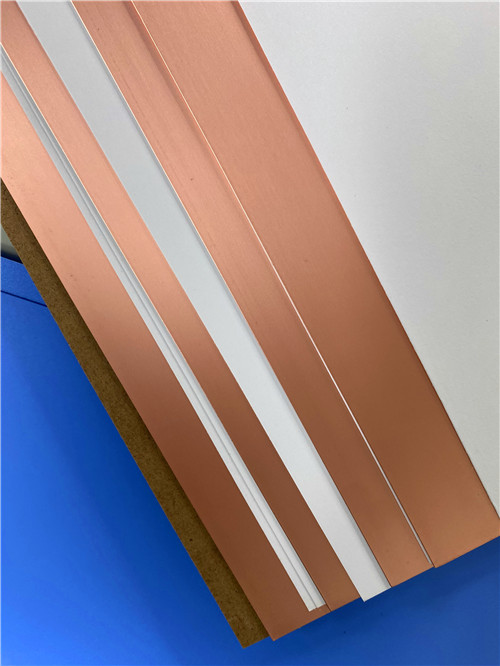


 Home
Home