


 Home
Home
What Are the 7 Types of PCB Testing Methods? Complete Guide
 September 15,2026
Printed Circuit Boards (PCBs) are the core carrier of all electronic equipment. Without strict quality testing, finished PCBs may suffer from open circuits, short circuits, poor conductivity, hidden reliability risks, and batch failure issues. For electronic engineers and procurement teams, understanding mainstream PCB testing methods is critical to verifying board quality, ensuring product stability, and avoiding mass production losses.
As a professional PCB manufacturer focusing on precision fabrication and quality control, we summarize the 7 most commonly used and authoritative PCB testing methods in the electronics industry. This guide explains their principles, applicable scenarios, advantages, and functions to help global clients clearly understand PCB quality inspection standards.
1. Quick Overview of 7 PCB Testing Methods
PCB testing runs through prototype verification, sample inspection and mass production quality control. The following concise comparison table intuitively shows the core functions of each test method, which supports one-click copying to Word for project reference and supplier evaluation.
Testing Method |
Core Function |
Main Application |
Visual Inspection |
Check appearance defects, dimensional errors, and surface anomalies |
Full-batch routine appearance inspection |
AOI Testing |
Automatic optical scanning to find tiny circuit defects |
High-precision board mass production inspection |
Continuity Testing |
Verify circuit conduction and avoid open/short circuits |
Basic electrical performance verification |
Flying Probe Testing |
High-precision electrical testing without custom fixtures |
Prototypes, small batches, complex multilayer boards |
Fixture Testing (ICT) |
Fast batch electrical testing with high efficiency |
Large-scale mass production PCB orders |
Impedance Testing |
Verify impedance tolerance of high-speed signal lines |
High-frequency, high-speed precision PCBs |
Reliability Environmental Testing |
Simulate extreme environments to verify long-term stability |
Industrial, automotive, and medical-grade PCBs |
2. Detailed Introduction to 7 PCB Testing Methods
2.1 Visual Inspection
Visual inspection is the most fundamental and initial step of PCB quality control. Inspectors check finished boards manually or with auxiliary magnifying equipment to identify obvious appearance and structural defects.
Main inspection items:Scratches, solder mask leakage, silkscreen offset, board edge burrs, dimensional deviation, missing pads, and surface contamination. This test eliminates basic defective boards before advanced electrical testing, improving overall testing efficiency.
2.2 AOI (Automatic Optical Inspection) Testing
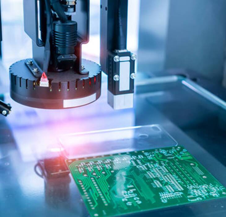
AOI testing is an automated high-precision optical detection technology, which is widely used in modern PCB mass production. The equipment scans the PCB surface with high-resolution cameras and compares it with standard design files to intelligently identify tiny defects that are invisible to the naked eye.
Main detection items:Fine line open/short circuits, trace width inconsistency, tiny copper residues, solder mask defects, and pad oxidation. It greatly improves the accuracy and consistency of mass production quality inspection.
2.3 Continuity Testing
Continuity testing is the basic electrical performance test for all PCBs. It mainly verifies whether the circuit conduction relationship is consistent with the design file.
Main detection items:Open circuit caused by broken traces, short circuit between adjacent lines, abnormal conduction of vias. This test ensures that the basic circuit function of the PCB is normal and eliminates boards with fatal electrical faults.
2.4 Flying Probe Testing
Flying probe test is a mainstream flexible electrical testing method for PCBs. It does not require custom test fixtures. The equipment uses two or multiple precision probes to move automatically and test each test point one by one according to Gerber files.
It is the preferred test method for PCB prototypes and small-batch orders, especially suitable for complex multilayer boards, high-density interconnect boards, and high-frequency boards. The disadvantage is relatively slow testing speed, so it is not suitable for super-large batch production.
2.5 ICT Fixture Testing
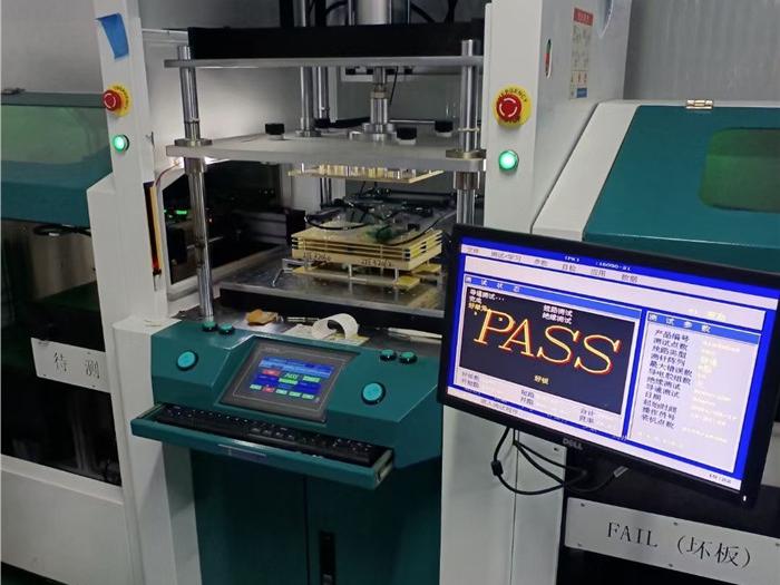
ICT (In-Circuit Test) fixture testing requires custom professional test fixtures according to PCB layout. It can complete full-point electrical testing of PCBs in a very short time with extremely high efficiency.
This method is mainly used for large-scale mass production PCB orders. Although the fixture customization takes time and cost, it can greatly reduce the unit testing cost and improve delivery efficiency for long-term bulk orders.
2.6 Impedance Testing
Impedance testing is a professional customized test for high-speed and high-frequency PCBs. In electronic design, specific signal lines need to maintain fixed impedance values to ensure signal integrity and avoid signal reflection and attenuation.
Professional manufacturers use precision impedance testers to detect the impedance value of key lines and confirm whether it is within the customer’s tolerance range. This test is essential for communication equipment, automotive electronics, and industrial control high-precision PCBs.
2.7 Reliability Environmental Testing
Environmental reliability testing is a high-standard durability verification for high-grade PCBs, simulating complex and extreme application environments to detect the long-term stability of boards.
Common test types:High and low temperature cycle test, humidity and heat resistance test, thermal shock test, salt spray test. It is mainly applicable to automotive-grade, medical-grade, aerospace and industrial-grade PCBs, ensuring that the boards can work stably in harsh environments for a long time.
3. How We Ensure PCB Quality Through Standard Testing
As a professional PCB manufacturer, we strictly implement multi-level testing procedures for all orders from prototype to mass production. We do not provide PCB design services, but fully restore customer design files with high precision and guarantee product quality through complete testing systems.
Our conventional delivery inspection includes visual inspection + AOI optical inspection + continuity test. For high-precision and high-frequency boards, we support customized impedance testing. For industrial and automotive-grade orders, we support environmental reliability testing to meet different industry certification standards.
4. Conclusion
Each of the 7 PCB testing methods has its unique application scenario. Visual inspection and AOI ensure appearance and circuit precision; continuity, flying probe and ICT tests guarantee basic electrical performance; impedance test ensures high-speed signal stability; environmental test verifies long-term reliability.
A complete testing system is the core guarantee of PCB manufacturing quality. Choosing a manufacturer with standardized testing processes can effectively reduce product failure rates and project risks.
Professional PCB Manufacturing & Testing Service
If you have finished Gerber files and need high-quality PCB fabrication with complete quality testing support, our team provides one-stop manufacturing services including AOI inspection, flying probe testing, impedance testing, and strict batch quality control. We support prototype, small batch and mass production for global clients, with stable quality and fast delivery. Contact us for a customized quote today.