

 Home
Home
Why Do Many Power Supply PCBs Have Slot Holes?
When disassembling or designing PS PCBs—for AC-DC modules, industrial power controllers, or consumer chargers—you’ll often see narrow slot holes, typically between HV (e.g., AC input, rectifiers) and LV (e.g., control ICs, output regulators) regions, or around heat-generating components (MOSFETs, transformers).
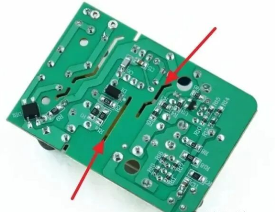
Figure 1: Typical Slot Hole Structure on Power Supply PCBs
Many assume these slots are merely for aesthetics or mechanical purposes. In reality, their true function is closely tied to electrical safety—centered on a key concept: Creepage Distance.
1. What is "Creepage Distance"?
Creepage distance refers to the shortest "leakage path" between two conductors along the surface of an insulator.
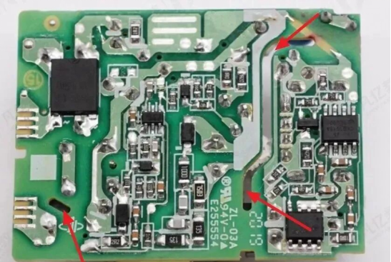
Figure 2: Schematic of Creepage Path and Insulation
A vivid analogy:
Imagine an ant crawling from one live conductor to another—restricted to moving along the insulator’s surface. The shortest path it takes is the "creepage distance."
![]()
Figure 3: Difference Between Creepage Distance and Clearance
Key Distinction:
- Creepage Distance: Path along the insulator surface (affected by dust/contamination).
- Clearance: Shortest straight-line path through the air (no surface contact).
2. Why Do Slots Extend Creepage Distance?
Power supply PCBs require strict isolation between high-voltage and low-voltage components.
However, space constraints often prevent achieving the required creepage distance between these components. So, what’s the solution?
Answer: Add slots! Cutting grooves in the PCB substrate is equivalent to "blocking the ant’s path"—artificially extending the surface creepage distance while effectively interrupting discharge channels on the insulation surface, thereby enhancing insulation performance.
3. Key Design Considerations for Slots
- Slot width: Recommended ≥1mm.
- Avoid copper pouring in high-voltage areas.
- Keep slots away from signal paths or critical traces.
- Ensure smooth slot edges to prevent corona discharge at sharp corners.
4. Common Application Scenarios
- AC-DC switching power supply modules.
- High-voltage driver circuits in industrial controllers.
- Mixed-voltage systems (e.g., 220V and 5V on the same PCB).
Whether to meet safety standards, address pollution degree requirements, or comply with insulation class specifications, rational slot design is an indispensable step in power supply PCB engineering.
5. Conclusion
Don’t overlook the "slot holes" on power supply PCBs—they’re far from unnecessary decorations. Instead, they’re a critical safeguard for your products to pass safety certification tests.