


 Home
-
Taconic PCB
-
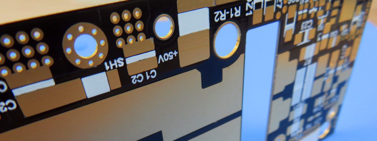
Taconic TLY-5 Double-Layer EPIG Finish PCB 7.5mil Low Dk TLY-5 Substrate for 77GHz Automotive Radar and Aerospace Avionics
Home
-
Taconic PCB
-
Taconic TLY-5 Double-Layer EPIG Finish PCB 7.5mil Low Dk TLY-5 Substrate for 77GHz Automotive Radar and Aerospace Avionics
Taconic TLY-5 Double-Layer EPIG Finish PCB 7.5mil Low Dk TLY-5 Substrate for 77GHz Automotive Radar and Aerospace Avionics
Printed Circuit Boards are custom-made products; the images and specifications provided are for reference only.
1. Introduction
Taconic TLY-5 PCB is a premium 2-Layer rigid high-frequency printed circuit board built around 7.5mil lightweight woven fiberglass PTFE dielectric core, classified as avionics and aerospace-grade ultra-low Dk base material. This 0.3mm finished-thickness circuit board features EPIG surface finish, adheres fully to IPC-Class-2 manufacturing standards, and supports worldwide mass production and delivery. Compared with chopped-fiber PTFE composite alternatives, the woven glass matrix of TLY-5 delivers outstanding dimensional stability and high production yield, while its ultra-low dissipation factor makes it perfectly fit for 77GHz automotive radar, millimeter-wave antennas, satellite communication and avionics phased array hardware. OEM side-by-side testing at 77GHz verifies TLY-5 laminate achieves equivalent insertion loss and dielectric performance against rival chopped fiber laminates, with drastically improved fabrication pass rates. The substrate also supports laser ablation processing and customizable Dk within 2.17–2.40 with tight ±0.02 tolerance, satisfying diverse Ka/E/W-band RF design demands.

2. Core Electrical & Mechanical Features of Taconic TLY-5 PCB
- Tunable Dielectric Constant (Dk): 2.17–2.40, tight tolerance ±0.02 at 10 GHz / 23°C
- Ultra-low Loss Tangent (Df): 0.0009 measured at 10GHz
- Material Density: 2.19 g/cm³
- Minimal Moisture Absorption: 0.02%
- Three-axis CTE performance: X-axis 26 ppm/°C, Y-axis 15 ppm/°C, Z-axis 217 ppm/°C
- Lightweight woven fiberglass reinforcement for superior mechanical stability
- Laser ablatable dielectric for efficient laser via fabrication
- Consistent batch-to-batch dielectric uniformity for repeatable RF performance
- Excellent copper foil adhesion with robust peel strength
3. Key Product Advantages
- Excellent dimensional stability minimizes dimensional offset during high-volume PCB fabrication
- Industry-leading lowest Df cuts millimeter-wave signal insertion loss for radar and communication modules
- High copper peel strength effectively prevents copper foil delamination during soldering and long-term service
- Ultra-low moisture absorption avoids electrical parameter drift under variable humidity environments
- Uniform, tightly controlled Dk ensures steady signal integrity across mass production batches
- Laser ablatable property simplifies precision laser via formation for compact RF circuit layouts
- EPIG surface finish delivers stable solderability and corrosion resistance for SMT assembly
- Full 100% electrical testing prior to shipment guarantees complete circuit connectivity compliance
4.PCB Construction Details
| Item | Specification |
| Base Material | Taconic TLY-5, 7.5mil (0.191 mm) low Dk aerospace-grade dielectric core |
| Layer Count | 2-Layers, Rigid PCB |
| Board Dimension | 45mm × 87mm, ±0.15mm tolerance, 1PCS standard size |
| Minimum Trace / Space | 6 mils / 10 mils |
| Minimum Hole Size | 0.4mm |
| Via Type | No Blind Vias, only through vias |
| Finished Board Thickness | 0.3mm |
| Outer Copper Weight | 1oz (1.4 mils) |
| Via Plating Thickness | 20 μm |
| Surface Finish | EPIG |
| Top Silkscreen | None |
| Bottom Silkscreen | None |
| Top Solder Mask | None |
| Bottom Solder Mask | None |
| Pre-Shipment Inspection | 100% Electrical Test |
5.PCB Stackup
2-Layer rigid PCB layer structure from top to bottom:
- Copper Layer 1: 35 μm
- TLY-5 Dielectric Core: 0.191 mm (7.5mil)
- Copper Layer 2: 35 μm
6. PCB Statistics
- Total Components: 37
- Total Pads: 149
- Through Hole Pads: 85
- Top SMT Pads: 64
- Bottom SMT Pads: 0
- Conductive Vias: 139
- Electrical Nets: 2
7. Artwork & Manufacturing Standard
- Supplied Artwork Format: Gerber RS-274-X
- Accepted Quality Standard: IPC-Class-2
- Supply Scope: Worldwide Production & Global Shipping Support
8. Typical Application Scenarios
- 77GHz automotive radar sensor circuit boards
- Satellite and cellular communication antenna assemblies
- RF power amplifier modules
- LNB, LNA and LNC millimeter-wave signal hardware
- Aerospace & avionics high-frequency electronic equipment
- Ka-band, E-band and W-band filters, couplers & phased array antennas
9. Taconic TLY-5 Copper Clad Laminate Knowledge
9.1 TLY-5 Laminate Full Technical Overview
Classified as avionics and aerospace-grade ultra-low Dk copper clad laminate, Taconic TLY-5 adopts ultra-lightweight woven fiberglass as reinforcing filler. Its woven glass matrix delivers far superior dimensional stability compared with conventional chopped fiber PTFE composite substrates, making it highly suitable for large-scale automated PCB manufacturing. Its ultra-low dissipation factor enables reliable performance on 77GHz automotive radar sensors and all mainstream millimeter-wave antenna systems.
Independent OEM comparative testing at 77GHz confirms lightly reinforced TLY-5 matches competing chopped fiber laminates in insertion loss and dielectric characteristics, while delivering significantly higher manufacturing yields. Its dielectric constant covers a customizable range of 2.17 to 2.40; most dielectric thicknesses support specified Dk values with ±0.02 tight tolerance. Within low Dk spectrum, the material maintains an ultra-low loss tangent of roughly 0.0009 at 10 GHz. Common end uses include satellite communication hardware, automotive radar boards, RF filters, directional couplers, avionics devices and phased array antenna systems.
 TLY-5.jpg)
9.2 Core Performance Benefits of TLY-5 CCL
- Superior dimensional stability for precision RF PCB fabrication
- Industry-low dissipation factor to reduce millimeter-wave power attenuation
- High copper peel strength to avoid copper layer separation
- Minimal moisture absorption to lock stable electrical performance
- Uniform, consistent Dk across production batches
- Laser ablatable dielectric for streamlined laser via processing
9.3 TLY-3FF Flexible Laminate Supplementary Introduction
TLY-3FF is a newly developed high-flexibility fiberglass-reinforced laminate, engineered for projects requiring specific bend radii. It boasts far greater flexibility than standard rigid TLY-5 substrates, with bend performance comparable to chopped fiber PTFE laminates. Meanwhile, TLY-3FF features a lower loss tangent than traditional chopped fiber alternatives.
This unique fiberglass-reinforced design retains the outstanding dimensional stability signature of standard TLY-5 series, while offering the mechanical flexibility of chopped fiber PTFE materials. Additionally, TLY-3FF is optimized for enhanced laser via forming capability over conventional glass-reinforced TLY-5 variants.
9.4 Universal Application Range for TLY Series Laminates
- Automotive 77GHz radar PCBs
- Satellite & cellular communication antenna circuit boards
- RF power amplifier modules
- LNBs, LNAs, LNCs millimeter-wave assemblies
- Aerospace and avionics high-frequency electronics
- Ka band, E band, W band RF filters, couplers & phased array antennas
10.Summary
Taconic 2-Layer TLY-5 High Frequency PCB integrates aerospace-grade low Dk dielectric performance and stable mechanical properties for millimeter-wave RF and avionics devices. Built on 7.5mil lightweight woven fiberglass PTFE core with customizable Dk 2.17–2.40 and ultra-low Df 0.0009, this 0.3mm thin PCB adopts EPIG surface finish and complies with IPC-Class-2 standards for global supply. Featuring laser ablatable structure, high copper peel strength and exceptional dimensional stability, it outperforms chopped fiber PTFE substrates in production yield, acting as an ideal base material for automotive radar, satellite communication, power amplifiers, avionics and Ka/E/W-band phased array antenna projects
11.Taconic TLY-5 Datasheet
| Properties | Conditions | Typical Value | Unit | Test Method |
| Electrical Properties | ||||
| Dielectric Constant | @ 10 GHz | 2.20 | — | IPC-650 2.5.5.5 |
| Dissipation Factor | @ 10 GHz | 0.0009 | — | IPC-650 2.5.5.5 |
| Volume Resistivity | After elevated temp. | 10¹⁰ | Mohms/cm | IPC-650 2.5.17.1 |
| Volume Resistivity | After humidity | 10¹⁰ | Mohms/cm | IPC-650 2.5.17.1 |
| Surface Resistivity | After elevated temp. | 10⁸ | Mohms | IPC-650 2.5.17.1 |
| Surface Resistivity | After humidity | 10⁸ | Mohms | IPC-650 2.5.17.1 |
| Thermal Properties | ||||
| Thermal Conductivity | — | 0.22 | W/m·K | ASTM F 433 |
| CTE (25–260°C) | X-axis | 26 | ppm/°C | ASTM D 3386 (TMA) |
| CTE (25–260°C) | Y-axis | 15 | ppm/°C | ASTM D 3386 (TMA) |
| CTE (25–260°C) | Z-axis | 217 | ppm/°C | ASTM D 3386 (TMA) |
| Mechanical Properties | ||||
| Peel Strength | 1/2 oz. ED copper | 1.96 (11) | N/mm (lbs/in) | IPC-650 2.4.8 |
| Peel Strength | 1 oz. CL1 copper | 2.86 (16) | N/mm (lbs/in) | IPC-650 2.4.8 |
| Peel Strength | 1 oz. C1 copper | 3.04 (17) | N/mm (lbs/in) | IPC-650 2.4.8 |
| Peel Strength | At elevated temp. | 2.32 (13) | N/mm (lbs/in) | IPC-650 2.4.8 |
| Flexural Strength | MD | 96.91 (14,057) | N/mm² (psi) | IPC-650 2.4.4 |
| Flexural Strength | CD | 89.32 (12,955) | N/mm² (psi) | IPC-650 2.4.4 |
| Young's Modulus | MD | 9.65 × 10³ (1.4 × 10⁶) | N/mm² (psi) | ASTM D 3039 / IPC-650 2.4.19 |
| Poisson's Ratio | MD | 0.21 | — | ASTM D 3039 / IPC-650 2.4.19 |
| Physical Properties | ||||
| Density (Specific Gravity) | — | 2.19 | g/cm³ | ASTM D 792 |
| Dimensional Stability | MD, 10 mil | -0.038 | mm/M (mils/in) | IPC-650 2.4.39 |
| Dimensional Stability | CD, 10 mil | -0.038 | mm/M (mils/in) | IPC-650 2.4.39 |
| Chemical / Physical Properties | ||||
| Moisture Absorption | — | 0.02 | % | IPC-650 2.6.2.1 |
| NASA Outgassing | TML | 0.01 | % | — |
| NASA Outgassing | CVCM | 0.01 | % | — |
| NASA Outgassing | WVR | 0.01 | % | — |
| UL-94 Flammability Rating | — | V-0 | — | UL-94 |