


 Home
-
Rogers PCB
-
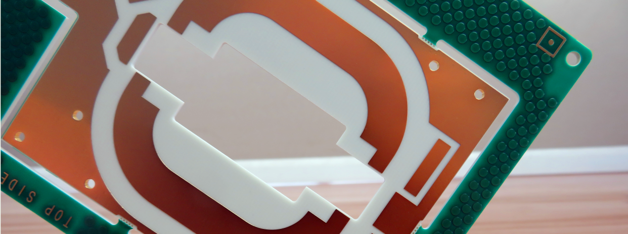
TMM10 2-Layer High Frequency PCB Built on Rogers 5.08mm Substrate with ENIG For Chip Tester and GPS Antenna
TMM10 2-Layer High Frequency PCB Built on Rogers 5.08mm Substrate with ENIG For Chip Tester and GPS Antenna
Printed Circuit Boards are custom-made products; the images and specifications provided are for reference only.
1. TMM10 PCB Material Introduction
TMM10 high-frequency rigid PCB adopts advanced thermoset microwave substrate material that integrates dual advantages of traditional PTFE and ceramic-based dielectrics. Rogers TMM10 high frequency circuit material breaks through the mechanical limitations and complex production restrictions of conventional high-frequency substrates, delivering excellent electrical repeatability and superior mechanical durability. As a high-performance composite microwave material, TMM10 RF PCB balances stable dielectric performance and friendly processability, making it a versatile and cost-effective solution for high-reliability microwave testing, satellite communication and precision antenna circuit designs.

2. Core Features of TMM10 PCB
- Stable Dielectric Constant: TMM10 PCB features a stable dielectric constant (Dk) of 9.20 ± 0.230, providing fixed and predictable electrical performance for high-frequency microwave circuit design and simulation.
- Ultra-Low Dissipation Factor: Rogers TMM10 high frequency PCB achieves an extremely low dissipation factor of 0.0022 at 10GHz, effectively minimizing high-frequency signal attenuation and ensuring efficient signal transmission.
- Low Thermal Coefficient of Dk: Equipped with a thermal coefficient of dielectric constant at -38 ppm/°K, TMM10 PCB maintains steady electrical parameters under drastic temperature changes, avoiding frequency drift and signal instability.
- Copper-Matched Thermal Expansion: TMM10 laminate provides well-matched CTE performance with copper foil, greatly improving structural stability and plated through-hole reliability during thermal cycling.
- High Thermal Decomposition Temperature: TMM10 PCB material owns a TGA decomposition temperature up to 425°C, supporting high-temperature fabrication and long-term high-power operation.
- Isotropic XYZ Thermal Expansion: Uniform CTE parameters of 21ppm/K (X-axis), 21ppm/K (Y-axis) and 20ppm/K (Z-axis) deliver balanced structural stress and minimal board deformation.
- Excellent Thermal Conductivity: With a thermal conductivity of 0.76W/mk, TMM10 RF PCB accelerates internal heat dissipation and improves high-power circuit endurance.
- Rich Thickness Specification: TMM10 laminate supports thickness ranges from 0.0015 inches to 0.500 inches with tight tolerance of ±0.0015 inches, meeting diverse stackup and design demands for customized TMM10 PCB.
3. Functional Benefits of TMM10 PCB
- Superior Mechanical Anti-Deformation Performance: TMM10 PCB material effectively resists creep and cold flow under long-term working loads, maintaining stable board flatness and structural integrity in complex working environments.
- Strong Chemical Process Resistance: TMM10 high frequency PCB features excellent resistance to various process chemicals and etching solutions, reducing substrate damage and lowering production defect rates during PCB fabrication.
- Simplified Plating Process: TMM10 RF PCB does not require sodium napthanate pretreatment before electroless plating, greatly simplifying production procedures and improving manufacturing efficiency.
- Reliable Wire-Bonding Capability: Built on high-stability thermoset resin system, TMM10 PCB supports precise and durable wire bonding without pad peeling or substrate deformation, ideal for high-precision chip testing modules.
4. PCB Construction Details
| Parameter Item | Specific Specifications |
| Base Material | Rogers TMM10 High Frequency Laminate |
| Layer Count | 2-Layer Double Sided Rigid High Frequency PCB |
| Board Dimensions | 63.9mm x 48mm (1PCS), Tolerance ±0.15mm |
| Minimum Trace/Space | 4/7 mils |
| Minimum Hole Size | 0.25mm |
| Blind Vias Design | No Blind Vias |
| Finished Board Thickness | 5.1mm |
| Finished Copper Weight | 1oz (1.4 mils) Outer Layers |
| Via Plating Thickness | 20 μm |
| Surface Finish | ENIG (Electroless Nickel Immersion Gold) |
| Top Silkscreen | No Silkscreen |
| Bottom Silkscreen | No Silkscreen |
| Top Solder Mask | No Solder Mask |
| Bottom Solder Mask | No Solder Mask |
| Pre-Shipment Test Standard | 100% Electrical Testing Before Shipment |
5. TMM10 PCB Stackup Structure
TMM10 double sided circuit board adopts a solid and symmetrical single-core stackup structure, delivering ultra-high structural stability and uniform electrical performance for high-precision microwave applications:
- Copper Layer 1 – 35 μm
- Rogers TMM10 Core Substrate – 5.08 mm (5.08mm)
- Copper Layer 2 – 35 μm
6. TMM10 PCB Statistical Parameters
Rogers TMM10 PCB board features precise and compact circuit layout configuration, meeting high-precision assembly and testing requirements for microwave and satellite devices:
- Total Components: 26
- Total Pads: 38
- Thru Hole Pads: 21
- Top SMT Pads: 17
- Bottom SMT Pads: 0
- Total Vias: 13
- Total Nets: 2
7. Production Artwork & Quality Standard of TMM10 PCB
TMM10 high frequency PCB uses standard Gerber RS-274-X production artwork, which is fully compatible with global professional PCB manufacturing equipment. All production, inspection and quality control procedures strictly comply with IPC-Class-2 quality standards to ensure stable consistency, high precision and long-term reliability of finished TMM10 PCB products. This product supports worldwide supply, providing reliable high-frequency circuit solutions for global satellite communication, antenna and chip testing industries.
8. Typical Application Fields of TMM10 PCB
With ultra-stable dielectric performance, high thermal resistance, excellent mechanical stability and chemical corrosion resistance, TMM10 PCB is widely deployed in high-precision and high-reliability microwave and satellite systems:
- High-Precision Chip Testing Equipment
- Microwave Dielectric Polarizer Devices
- Satellite Communication System Circuits
- GPS Antenna and Patch Antenna Modules
- High-Reliability Microwave RF Circuit Systems
9. DataSheet
| Properties | Typical Value | Direction | Units | Test Conditions | Test Method |
| Electrical Properties | |||||
| Dielectric Constant (process) | 9.20 ± 0.230 | Z | – | 10 GHz | IPC-TM-650 2.5.5.5 |
| Dielectric Constant (design) | 9.8 | – | – | 8 GHz – 40 GHz | Differential Phase Length Method |
| Dissipation Factor (process) | 0.0022 | Z | – | 10 GHz | IPC-TM-650 2.5.5.5 |
| Thermal Coefficient of Dielectric Constant | -38 | – | ppm/°K | -55 to +125°C | IPC-TM-650 2.5.5.5 |
| Insulation Resistance | >2000 | – | Gohm | C/96/60/95 | ASTM D257 |
| Volume Resistivity | 2×10⁸ | – | MΩ·cm | – | ASTM D257 |
| Surface Resistivity | 4×10⁷ | – | MΩ | – | ASTM D257 |
| Electrical Strength (Dielectric Strength) | 285 | Z | V/mil | – | IPC-TM-650 2.5.6.2 |
| Thermal Properties | |||||
| Decomposition Temperature (Td) | 425 | – | °C | TGA | ASTM D3850 |
| Coefficient of Thermal Expansion – x | 21 | X | ppm/K | 0 to 140°C | ASTM E 831, IPC-TM-650 2.4.41 |
| Coefficient of Thermal Expansion – y | 21 | Y | ppm/K | 0 to 140°C | ASTM E 831, IPC-TM-650 2.4.41 |
| Coefficient of Thermal Expansion – z | 20 | Z | ppm/K | 0 to 140°C | ASTM E 831, IPC-TM-650 2.4.41 |
| Thermal Conductivity | 0.76 | Z | W/m/K | 80°C | ASTM C518 |
| Mechanical Properties | |||||
| Copper Peel Strength after Thermal Stress | 5.0 (0.9) | X,Y | lb/inch (N/mm) | After solder float, 1 oz. EDC | IPC-TM-650 2.4.8 |
| Flexural Strength (MD/CMD) | 13.62 | X,Y | kpsi | A | ASTM D790 |
| Flexural Modulus (MD/CMD) | 1.79 | X,Y | Mpsi | A | ASTM D790 |
| General Properties | |||||
| Moisture Absorption (1.27 mm / 0.050”) | 0.09 | – | % | D/24/23 | ASTM D570 |
| Moisture Absorption (3.18 mm / 0.125”) | 0.20 | – | % | D/24/23 | ASTM D570 |
| Specific Gravity | 2.77 | – | – | A | ASTM D792 |
| Specific Heat Capacity | 0.74 | – | J/g/K | A | Calculated |
| Lead-Free Process Compatible | YES | – | – | – | – |
10. TMM10 Copper Clad Laminate Knowledge
Rogers TMM series thermoset microwave CCL (Copper Clad Laminate) is high-performance composite dielectric material specially developed for high-reliability stripline and microstrip TMM10 PCB designs. Formulated with ceramic filler, hydrocarbon components and thermoset polymer resin, TMM10 laminate perfectly combines the core advantages of traditional PTFE substrates and ceramic substrates while avoiding their respective processing defects. TMM10 PCB substrate provides balanced electrical stability and mechanical rigidity, becoming an ideal substrate for mass production of high-precision TMM10 high frequency PCB.
10.1 Key Properties of TMM Series CCL
- Ultra-Stable Dielectric Temperature Performance: TMM series Laminate owns extremely low thermal coefficient of dielectric constant below 30 ppm/°C, enabling TMM10 PCB to maintain consistent electrical performance under severe temperature fluctuation environments.
- Copper-Matched Isotropic CTE: Uniform thermal expansion coefficient matches copper foil perfectly, effectively improving plated through-hole reliability and minimizing etching shrinkage for high-precision TMM10 PCB circuit patterns.
- Efficient Thermal Dissipation: Thermal conductivity is nearly twice higher than conventional PTFE ceramic laminates, allowing TMM10 RF PCB to quickly export internal heat and adapt to high-power microwave circuit operation.
- High-Temperature Structural Rigidity: Thermoset resin base maintains stable rigidity under high-temperature conditions, supporting reliable wire bonding without pad warpage or substrate deformation on TMM10 PCB.
- Excellent Chemical Compatibility: TMM10 high-frequency laminate resists common PCB etching agents and processing solvents, fully adapting to standard PCB fabrication processes and improving production yield of TMM10 PCB.
10.2 Available Specifications of TMM Series Laminate
- Diversified Dielectric Constant Options: Multiple Dk value specifications cover diverse high-frequency design requirements, greatly reducing design difficulty for customized TMM10 PCB projects.
- Adjustable Copper Foil Weight: Supports copper foil ranges from 1/2 oz/ft² to 2 oz/ft², flexible for different current load and signal transmission demands of TMM10 RF PCB.
- Metal Plate Bonding Capability: TMM10 laminate can be directly bonded with brass or aluminum plates to enhance overall structural strength and heat dissipation performance of TMM10 PCB assemblies.
- Rich Thickness Coverage: Substrate thickness ranges from 0.015 inches to 0.500 inches, fully meeting various stackup and thickness design standards for TMM10 high frequency PCB.
10.3 Core Features & Application Advantages
- Simplified High-Frequency Design: Rich dielectric constant options support single-material system design, effectively reducing structural complexity of TMM10 PCB microwave circuits.
- Superior Long-Term Stability: Outstanding creep resistance and cold flow resistance ensure TMM10 PCB maintains stable structure and performance in long-term harsh operation scenarios.
- High Structural & Assembly Reliability: Copper-matched CTE greatly reduces thermal deformation risk and improves overall durability of TMM10 high frequency PCB.
- Cost-Effective Fabrication: Strong chemical resistance lowers processing damage and defect rate, effectively reducing overall manufacturing cost of TMM10 RF PCB.
- Versatile Replacement Capability: Stable thermoset structure supports professional wire bonding, and TMM10 laminate can directly replace expensive alumina substrates, achieving significant cost savings for high-precision microwave PCB projects.
11. Summary
TMM10 2-Layer PCB is a high-reliability thick-core microwave circuit board built on 5.08 mm Rogers TMM10 thermoset ceramic composite laminate. This double-sided TMM10 PCB adopts pure ENIG surface finish with no solder mask and no silkscreen, realizing ultra-clean surface conductivity for high-precision microwave signal testing and transmission. Equipped with 1oz full outer copper layer, 0.25mm ultra-small drilling capability and 20μm uniform via plating, TMM10 high frequency microwave material delivers excellent circuit precision and assembly compatibility. With ultra-low dielectric loss, copper-matched thermal expansion, high thermal conductivity and outstanding chemical stability, TMM10 RF PCB perfectly adapts to chip testing, satellite communication and GPS antenna system applications, serving as a high-stability and cost-effective high-frequency circuit solution for global microwave industries.