


 Home
-
Rogers PCB
-
Rogers RO3006 Double-Layer OSP High Frequency PCB 5mil Ceramic-Filled PTFE Low Loss PCB for Automotive Radar & Telecommunication
Home
-
Rogers PCB
-
Rogers RO3006 Double-Layer OSP High Frequency PCB 5mil Ceramic-Filled PTFE Low Loss PCB for Automotive Radar & Telecommunication
Rogers RO3006 Double-Layer OSP High Frequency PCB 5mil Ceramic-Filled PTFE Low Loss PCB for Automotive Radar & Telecommunication
Printed Circuit Boards are custom-made products; the images and specifications provided are for reference only.
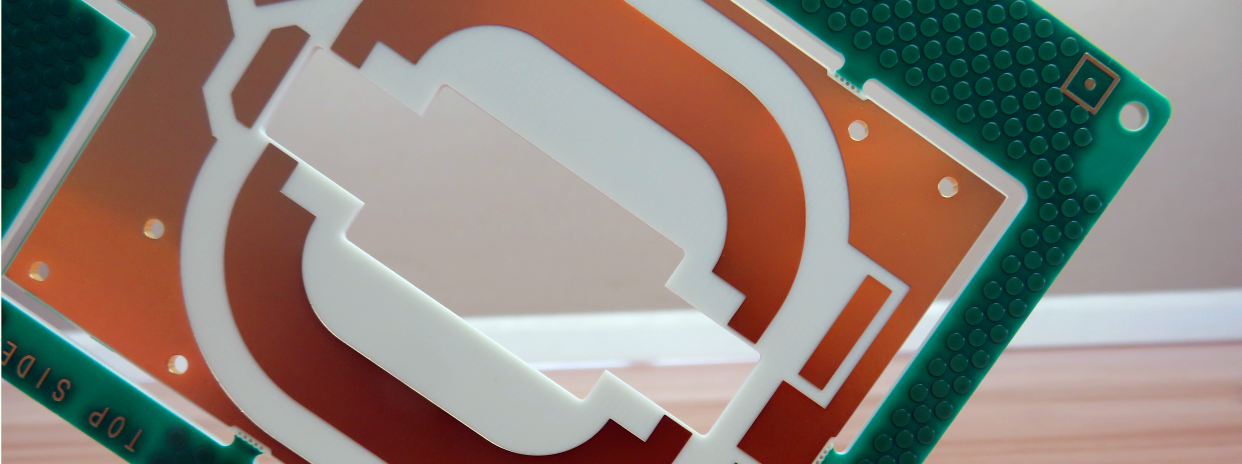
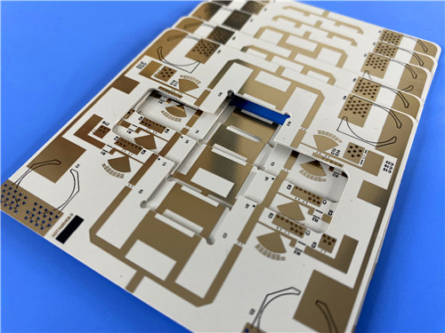
Rogers RO3006 2-layer rigid PCB is a ultra-thin high-performance microwave circuit board built on authentic RO3000 series ceramic-filled PTFE composite substrates. Featuring an ultra-slim 0.25mm finished board thickness and reliable OSP surface finish, RO3006 precision RF PCB delivers excellent surface flatness, oxidation resistance and assembly adaptability for high-frequency circuit fabrication. Manufactured with standard Gerber RS-274-X artwork and compliant with strict IPC-Class-2 industrial standards, every board undergoes 100% full electrical testing before shipment to ensure zero defect circuit performance. Different from conventional glass-reinforced PTFE substrates with unstable dielectric parameters at room temperature, Rogers RO3006 high frequency material maintains consistent dielectric constant across variable temperature environments. With worldwide availability and cost-effective volume production advantages, Rogers RO3006 2-layer circuit board PCB serves as an ideal solution for automotive radar, satellite antenna, cellular communication and wireless microwave system applications.
2. Core Product Features
Equipped with premium Rogers RO3006 ceramic-filled PTFE composite material, this ultra-thin high frequency PCB integrates outstanding electrical stability, thermal performance and mechanical consistency, featuring comprehensive technical advantages for commercial RF and microwave designs:
- Adopts authentic Rogers RO3006 ceramic-filled PTFE composite laminate, featuring uniform material structure and stable batch performance
- Precise and stable dielectric constant of 6.15 ±0.15 at 10GHz and 23°C, eliminating room-temperature DK step change common to ordinary PTFE glass substrates
- Ultra-low dissipation factor of 0.002 at 10GHz, effectively minimizing high-frequency signal attenuation and transmission loss
- Superior thermal resistance with decomposition temperature Td exceeding 500°C, adapting to high-temperature processing and long-term high-power operation
- High thermal conductivity of 0.79 W/mK, improving heat dissipation efficiency for compact high-frequency circuit modules
- Extremely low moisture absorption rate of 0.02%, ensuring stable electrical performance in humid and variable environmental conditions
- Balanced low thermal expansion coefficient: 17 ppm/°C on X/Y axis and 24 ppm/°C on Z axis within -55°C to 288°C, realizing excellent dimensional stability
- No blind via design, simplifying processing technology and improving circuit reliability for standard high-frequency layouts
- Dual-side no solder mask and single-side black silkscreen design, meeting lightweight and high-precision assembly requirements
3. Product Performance Benefits
Benefiting from the exclusive ceramic-filled PTFE formula and optimized structural design of Rogers RO3006 RF substrate, this 2-layer ultra-thin high frequency PCB provides remarkable practical advantages for modern commercial high-frequency electronic design and mass production:
- Features uniform mechanical properties across diverse dielectric constant specifications, supporting flexible multi-layer PCB designs with mixed DK materials without causing board warpage or reliability risks
- Fully compatible with epoxy glass multi-layer hybrid PCB structures, greatly expanding design flexibility for composite high-frequency circuit boards
- Low in-plane CTE matches copper foil expansion characteristics perfectly, significantly improving surface mount assembly accuracy and long-term structural reliability
- Excellent temperature resistance and dimensional stability, ideal for temperature-sensitive high-frequency circuits that require stable phase and frequency performance
- Maintains ultra-low etch shrinkage below 0.5 mils per inch after etching and baking, ensuring high precision of fine-line circuit layouts
- Stable Z-axis thermal expansion greatly enhances plated through-hole reliability, even in severe alternating thermal environments
- Supports standard PTFE PCB processing technology with minor adjustments, adapting to volume manufacturing and delivering economical laminate and production costs
- Ultra-low dielectric loss enables stable operation up to 77GHz, fully meeting the requirements of high-bandwidth microwave and millimeter-wave applications
4. PCB Construction Details
Rogers RO3006 ultra-thin high frequency PCB is fabricated with standardized high-precision manufacturing parameters. All detailed construction specifications are organized in the table below for circuit design, production processing and quality inspection reference:
| Technical Item | Detailed Specification |
| Board Dimensions | 43.66mm x 28.01mm (1PCS) |
| Minimum Trace / Space | 5/7 mils |
| Minimum Hole Size | 0.25mm |
| Blind Vias Design | No Blind Vias Applied |
| Finished Board Thickness | 0.25mm Ultra-Thin |
| Finished Outer Layer Copper Weight | 1oz (1.4 mils) |
| Via Plating Thickness | 20 μm |
| Surface Finish | OSP (Organic Solderability Preservative) |
| Top Silkscreen | Black |
| Bottom Silkscreen | No Silkscreen Printing |
| Top Solder Mask | No Solder Mask |
| Bottom Solder Mask | No Solder Mask |
| Pre-Shipment Inspection | 100% Full Electrical Performance Testing |
5. PCB Stackup Structure
Rogers RO3006 2-layer rigid ultra-thin PCB adopts a compact and stable layer stackup structure with genuine Rogers RO3006 core substrate and high-purity copper layers, ensuring balanced electrical transmission and structural stability for high-frequency operation:
- Copper_layer_1: 35 μm High-Purity Copper Foil
- Rogers RO3006 Core Substrate: 5mil (0.127mm) Ceramic-Filled PTFE Laminate
- Copper_layer_2: 35 μm High-Purity Copper Foil
6. PCB Circuit Statistics
Rogers RO3006 high frequency PCB board features a compact and refined circuit layout, with complete component assembly and wiring parameters to meet lightweight and high-precision wireless communication circuit requirements:
- Total Mountable Components: 20
- Total Circuit Pads: 24
- Through Hole Pads: 13
- Top SMT Pads: 11
- Bottom SMT Pads: 0
- Conductive Vias: 34
- Circuit Nets: 2
7. Production Standard & Global Availability
Rogers RO3006 high frequency PCB adopts standard Gerber RS-274-X artwork format, achieving universal compatibility with global PTFE PCB processing and assembly equipment. All production and inspection procedures strictly comply with IPC-Class-2 quality standards, guaranteeing excellent dimensional accuracy, stable dielectric performance and long-term structural reliability. Supported by mature global supply systems, this cost-effective high-frequency laminate PCB can provide standardized and customized solutions for commercial microwave, automotive electronics and wireless communication enterprises worldwide.
8. Typical Application Scenarios
Relying on ultra-low dielectric loss, stable temperature-frequency performance, low thermal expansion and high structural reliability, RO3006 high frequency PCB is widely applied in commercial high-frequency wireless and microwave electronic fields:
- Automotive Electronic Systems: High-precision automotive radar detection equipment
- Satellite Communication Devices: GPS satellite antennas and direct broadcast satellite terminal equipment
- Cellular Telecommunication Systems: Wireless base station power amplifiers and communication antennas
- Wireless Communication Modules: High-frequency patch antennas for short-range wireless transmission
- Industrial Communication Equipment: Cable system datalink modules, remote meter reading devices and power backplane systems
9. Rogers RO3006 & RO3000 Series Substrate Professional Knowledge
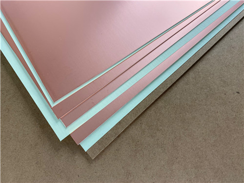
Rogers RO3006 is a core member of the premium RO3000 series ceramic-filled PTFE composite circuit materials, specially developed for cost-sensitive commercial microwave and RF applications. The series perfectly balances high-end high-frequency performance and economical mass production costs, becoming one of the most widely used high-reliability substrate materials in the commercial wireless communication industry.
9.1 Material Core Characteristics & Technical Breakthroughs
Different from traditional glass fiber reinforced PTFE laminates, RO3000 series materials adopt ceramic-filled PTFE composite formula, achieving completely consistent mechanical properties regardless of dielectric constant grades. This unique feature solves the industry pain point of board warpage and structural instability caused by mismatched material parameters in multi-layer mixed-DK PCB designs. RO3006 inherits the series’ core advantages, realizing ultra-stable dielectric constant output without step change near room temperature, ensuring consistent signal performance in variable temperature working environments.
9.2 Thermal Expansion & Dimensional Stability Advantages
RO3006 high-frequency circuit material features industry-optimized low CTE parameters, with X-axis and Y-axis thermal expansion coefficients of 17 ppm/°C, which is highly matched with copper foil expansion characteristics. This precise parameter matching greatly improves the reliability of SMT surface mount assembly and effectively avoids component desoldering or circuit deformation caused by temperature changes. The Z-axis CTE is controlled at 24 ppm/°C, providing exceptional plated through-hole reliability even under severe cyclic thermal shock conditions. Meanwhile, the material maintains ultra-low etching shrinkage below 0.5 mils per inch after etching and baking, ensuring ultra-high precision of fine-line high-frequency circuits.
9.3 Processing Performance & Production Compatibility
All RO3000 series laminates including RO3006 support standard industrial PTFE PCB processing technologies, with only minor process adjustments required for mass production. The excellent processing compatibility enables stable fabrication of multi-layer boards, hybrid epoxy-glass composite boards and high-density fine-line circuits. Benefiting from mature volume manufacturing processes, RO3006 laminates deliver outstanding cost performance, realizing high-end high-frequency performance at economical commercial prices.
9.4 Ultra-High Frequency Environmental Adaptability
With ultra-low dissipation factor, stable frequency-temperature characteristics and excellent thermal resistance, RO3006 material supports stable circuit operation up to 77GHz. Rogers RO3006 RF circuit board is highly suitable for high-precision high-frequency devices such as band-pass filters, microstrip patch antennas and voltage-controlled oscillators. The ultra-low moisture absorption and excellent thermal conductivity further enhance the environmental adaptability and service life of high-frequency circuit modules in complex working conditions.
10. Product Summary
Rogers RO3006 2-Layer high frequency PCB is an ultra-thin commercial-grade ceramic-filled PTFE rigid circuit board tailored for microwave and RF wireless applications. Featuring 0.25mm ultra-thin body, OSP surface treatment, stable DK 6.15 dielectric performance and ultra-low high-frequency loss, RO3006 2-layer PCB delivers copper-matched low thermal expansion, excellent dimensional stability and reliable multi-layer hybrid design compatibility. Compliant with IPC-Class-2 standards and 100% pre-delivery electrical testing, it supports high-precision fine-line processing and large-volume economical production. With global supply availability and superior high-frequency stability, it is the optimal choice for automotive radar, satellite communication, cellular base station antenna and industrial wireless microwave equipment manufacturing.
11. Rogers RO3006 Datasheet
| Properties | Typical Value | Units | Test Conditions | Test Method |
| Electrical Properties | ||||
| Dielectric Constant (process) | 6.15 ± 0.15 | — | 23°C, 10 GHz | IPC TM-650 2.5.5.5 |
| Dielectric Constant (design) | 6.50 | — | 8 GHz – 40 GHz | Differential Phase Length |
| Dissipation Factor | 0.0020 | — | 23°C, 10 GHz | IPC TM-650 2.5.5.5 |
| Thermal Coefficient of Dielectric Constant | -262 | ppm/°C | -50°C ~ 150°C, 10 GHz | IPC TM-650 2.5.5.5 |
| Volume Resistivity | 10⁵ | MΩ·cm | Condition A | IPC TM-650 2.5.17.1 |
| Surface Resistivity | 10⁵ | MΩ | Condition A | IPC TM-650 2.5.17.1 |
| Thermal Properties | ||||
| Decomposition Temperature (Td, TGA) | 500 | °C | — | ASTM D3850 |
| Coefficient of Thermal Expansion – X-axis | 17 | ppm/°C | -55°C ~ 288°C, 23°C / 50% RH | IPC TM-650 2.4.41 |
| Coefficient of Thermal Expansion – Y-axis | 17 | ppm/°C | -55°C ~ 288°C, 23°C / 50% RH | IPC TM-650 2.4.41 |
| Coefficient of Thermal Expansion – Z-axis | 24 | ppm/°C | -55°C ~ 288°C, 23°C / 50% RH | IPC TM-650 2.4.41 |
| Thermal Conductivity | 0.79 | W/(m·K) | 50°C | ASTM D5470 |
| Mechanical Properties | ||||
| Copper Peel Strength | 7.1 | lbs/in | 1 oz. EDC, After Solder Float | IPC TM-650 2.4.8 |
| Young’s Modulus | 14981293 | MPa | 23°C | ASTM D638 |
| Dimensional Stability (MD / CMD) | -0.27-0.15 | mm/m | Condition A | IPC TM-650 2.2.4 |
| Physical & Flame Properties | ||||
| Flammability | V-0 | — | — | UL 94 |
| Moisture Absorption | 0.02 | % | D48/50 | IPC TM-650 2.6.2.1 |
| Density | 2.6 | g/cm³ | 23°C | ASTM D792 |
| Specific Heat Capacity | 0.86 | J/g/K | — | Calculated |
| Lead Free Process Compatible | Yes | — | — | — |