


 Home
-
Rogers PCB
-
Rogers 4003 1100mm Extra Long PCB 32mil RO4003C RF Circuit Board with 1OZ Copper, Immersion Gold and No Silkscreen
Rogers 4003 1100mm Extra Long PCB 32mil RO4003C RF Circuit Board with 1OZ Copper, Immersion Gold and No Silkscreen
Printed Circuit Boards are custom-made products; the images and specifications provided are for reference only.
1.General Description
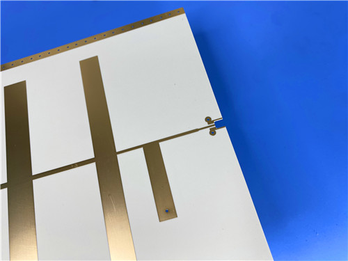
The Rogers RO4003C PCB is a 2-layer rigid printed circuit board built on 32mil 4003C high-frequency PCB laminates. Rogers 4003 extra long 1.1-meter PCB substrate is woven glass reinforced hydrocarbon ceramic composite material, which delivers PTFE-like electrical performance while retaining the simple manufacturability of FR-4 epoxy glass materials. Rogers 4003 printed circuit board supports large-format RF designs and can be processed with standard PCB fabrication workflows.
2. Features
- Extra long 1100mm x 350mm board dimension, 2-layer rigid PCB built on Rogers RO4003C laminate
- 32mil (0.813mm) base material, 1oz finished outer copper weight, 2u" immersion gold surface finish
- No solder mask and no silkscreen on both sides, clean bare circuit design
- Dielectric constant Dk of 3.38 +/-0.05, dissipation factor of 0.0027 at 10 GHz for low signal loss
- Low Z-axis thermal expansion coefficient at 46 ppm/°C, ensures stable dimensional performance
- 100% electrical test performed prior to shipment, available for worldwide supply
3. Benefits
- 1.1m ultra-long board size meets special large-format RF antenna and microwave circuit layout requirements
- RO4003C high-frequency laminates can be manufactured using standard FR-4 processes and lower production cost
- Excellent dimensional stability, well suited for multi-layer board constructions
- No special through-hole treatment required, unlike PTFE microwave material
- Tight Dk tolerance and low dielectric loss support performance-sensitive high-volume RF projects
4. PCB Construction Details
| Parameter | Specification |
| Base material | Rogers RO4003C |
| Layer count | 2 layers |
| Board dimensions | 1100mm x 350mm=1PCS, +/- 0.15mm |
| Finished board thickness | 0.813mm |
| Finished Cu weight | 1oz outer layers |
| Surface finish | Immersion gold, 2u" gold thickness |
| Top Silkscreen | No |
| Bottom Silkscreen | No |
| Top Solder Mask | No |
| Bottom Solder Mask | No |
| Pre-shipment Test | 100% Electrical test used prior to shipment |
5. PCB Stackup
- Copper_layer_1 - 35 μm
- Rogers RO4003C Core - 0.813 mm (32mil)
- Copper_layer_2 - 35 μm
6. Type of artwork supplied
Gerber RS-274-X
7. Quality standard
IPC-Class-2
8. Availability
worldwide
9. Rogers RO4000 Series Copper Clad Laminate (CCL) Introduction:
9.1 RO4003C Laminates Product Introduction
- Rogers 4003 PCB materials are proprietary woven glass reinforced hydrocarbon/ceramics. They provide electrical performance comparable to PTFE/woven glass materials and the manufacturability of epoxy/glass substrates.
- RO4003C laminates adopt 1080 and 1674 glass fabric styles. All variants maintain consistent electrical performance with tight dielectric constant control and low loss. The material uses standard epoxy/glass processing methods at lower cost than traditional microwave laminates.
- Different from PTFE based microwave materials, RO4003C does not need special through-hole treatments or complex handling procedures.
- Rogers 4003 circuit materials are non-brominated and not rated UL 94 V-0. Select RO4835 and RO4350B laminates for projects requiring UL 94 V-0 flame resistance.
9.2 Core Features of RO4000 Series CCL
- Reinforced hydrocarbon/ceramic laminate construction, not PTFE material
- Dk of 3.38 +/- 0.05 and low dissipation factor of 0.0027 at 10 GHz
- Low dielectric tolerance and low insertion loss for high-frequency signal transmission
- Stable electrical properties across a broad frequency range
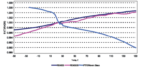
- Low thermal coefficient of dielectric constant and low Z-axis coefficient of thermal expansion
- Excellent dimensional stability and reliable plated through-hole performance
- High Tg >280°C, stable expansion characteristics over full PCB processing temperature range
- CAF resistant, compatible with standard FR-4 manufacturing workflow
- Supports LoPro foil option for further reduced insertion loss
RO4000 Series Materials Dk vs. Temperature
9.3 Processing & Structural Advantages of RO4000 Series CCL
- RO4000 high-frequency circuit materials deliver premium high-frequency performance with affordable fabrication cost
- Material CTE matches copper closely, ideal for mixed dielectric multi-layer board designs
- No sodium etch or specialized via preparation required, unlike PTFE high-frequency substrates
- Rigid thermoset laminate compatible with automated handling and copper surface scrubbing equipment
- RO4350B serves as a drop-in replacement for RO4003C and offers RoHS compliant UL 94V-0 flame retardant property
- RO4003C meets IPC-4103 slash sheet /10 standard
9.4 Main Application of RO4000 Series Laminate
- Cellular Base Station Antennas and Power Amplifiers
- RF Identification Tags
- Automotive Radar and Sensors
- LNB’s for Direct Broadcast Satellites
- Broadband RF circuits and controlled impedance transmission lines
- Filter and matching network designs for high frequency systems
9.5 Low Outgassing Characteristics of Rogers Laminates Approved for Spacecraft Applications
- RT/duroid composites made of PTFE with inorganic fiber filler and TMM temperature stable hydrocarbon composites deliver excellent resistance to outgassing, verified by test data following NASA test procedure SP-R-0022A.
- Reinforced PTFE laminates and PTFE composites feature stable thermal performance and consistent low outgassing properties. TMM temperature stable laminates are highly crosslinked hydrocarbon materials, and they will not release gas or chemical by-products under elevated temperature conditions.
- The test data shown in the table on the back page was obtained from sample specimens with copper foil fully etched away.
- This test method vacuum-heats 100 to 300 mg specimens inside a copper enclosure at 125°C for 24 hours. A chrome-plated collector kept at 25°C sits 12.7 mm away from the enclosure exit port.
- The test metrics include Total Mass Loss (TML), Collected Volatile Condensable Materials (CVCM) and Water Vapor Recovered (WVR), calculated as a percentage of the original specimen mass.
- Materials with TML below 1.0% and CVCM below 0.1% are generally classified as low outgassing materials and qualified for spacecraft applications.
- All Rogers laminate materials listed satisfy these strict low outgassing criteria for space-grade projects.
NASA Outgassing Results 125°C, ≤10-6 torr |
|||
Product |
"Total Mass Loss %" |
"Collected Volatiles %" |
"Water Vapor Recovered %" |
AD350A™ |
0.02 |
0.00 |
0.02 |
CLTE™ |
0.02 |
0.00 |
0.00 |
CLTE-AT™ |
0.04 |
0.00 |
0.00 |
CLTE-MW™ |
0.02 |
0.00 |
0.01 |
CLTE-XT™ |
0.02 |
0.00 |
0.01 |
COOLSPAN® |
0.22 |
0.02 |
0.05 |
CuClad® 217 |
0.01 |
0.01 |
0.00 |
CuClad 233 |
0.01 |
0.01 |
0.00 |
CuClad 250 |
0.01 |
0.00 |
0.00 |
CuClad 6250 |
0.32 |
0.05 |
0.00 |
CuClad 6700 |
0.13 |
0.01 |
0.02 |
DiClad® 880 |
0.02 |
0.00 |
0.01 |
DiClad 870 |
0.01 |
0.01 |
0.01 |
DiClad 527 |
0.02 |
0.00 |
0.01 |
IM™-880 |
0.01 |
0.01 |
|
IM-870 |
0.01 |
0.01 |
|
IM-300 |
0.01 |
0.01 |
|
IsoClad® 917 |
0.02 |
0.00 |
0.02 |
IsoClad 933 |
0.03 |
0.00 |
0.02 |
MAGTREX® |
0.02 |
0.02 |
0.02 |
RO3003™ |
0.10 |
<0.01 |
<0.01 |
RO3006™ |
0.02 |
0.03 |
0.01 |
NASA Outgassing Results 125°C, ≤10-6 torr |
|||
Product |
"Total Mass Loss %" |
"Collected Volatiles %" |
"Water Vapor Recovered %" |
RO3010™ |
<0.01 |
<0.01 |
<0.01 |
RO3210™ |
0.00 |
0.01 |
0.01 |
RO4003C™ |
0.06 |
0.00 |
0.02 |
RO4350B™ |
0.12 |
0.02 |
0.02 |
RO4360G2™ |
0.16 |
0.01 |
0.03 |
RO4450F™ |
0.37 |
0.05 |
0.02 |
RO4450T™ |
0.21 |
0.01 |
0.03 |
RO4460G2™ |
0.29 |
<0.01 |
0.04 |
RO4730G3™ |
0.12 |
|
0.05 |
RO4835™ |
0.02 |
<0.01 |
0.04 |
RT/duroid® 5870 |
0.02 |
<0.01 |
0.01 |
RT/duroid 5880 |
0.01 |
<0.01 |
0.02 |
RT/duroid 5880LZ |
0.01 |
0.01 |
0.02 |
RT/duroid 6002 |
0.03 |
<0.01 |
<0.01 |
RT/duroid 6006 |
0.01 |
<0.01 |
<0.01 |
RT/duroid 6010.2LM |
0.02 |
<0.01 |
<0.01 |
RT/duroid 6202 |
0.02 |
<0.01 |
<0.01 |
RT/duroid 6202PR |
0.02 |
0.01 |
0.02 |
RT/duroid 6035HTC |
0.01 |
<0.01 |
<0.01 |
SpeedWave® Pre- preg |
0.08 |
0.01 |
0.10 |
TMM®3 |
0.11 |
0.00 |
0.02 |
TMM4 |
0.07 |
0.00 |
0.02 |
TMM10 |
0.07 |
0.00 |
0.03 |
TMM10i |
0.04 |
0.00 |
0.01 |
Note: Reporting the WVR (water vapor recovered) value is optional according to https://outgassing.nasa.gov/og_desc.html
10. Some Typical Applications
- Cellular base station antennas and power amplifiers
- RF identification tags
- Automotive radar and sensors
- LNB’s for direct broadcast satellites
- Broadband RF & microwave circuitry
- High-frequency controlled impedance transmission line
11.RO4003C Properties
| Property | Typical Value | Direction | Units | Condition | Test Method |
| RO4003C | |||||
| Dielectric Constant, er Process | 3.38 ± 0.05 | Z | - | 10 GHz/23°C | IPC-TM-650 2.5.5.5 Clamped Stripline |
| Dielectric Constant, er Design | 3.55 | Z | - | 8 to 40 GHz | Differential Phase Length Method |
| Dissipation Factor tan d | 0.0027 | Z | - | 10 GHz/23°C | IPC-TM-650 2.5.5.5 |
| Dissipation Factor tan d | 0.0021 | Z | - | 2.5 GHz/23°C | IPC-TM-650 2.5.5.5 |
| Thermal Coefficient of e | +40 | Z | ppm/°C | -50°C to 150°C | IPC-TM-650 2.5.5.5 |
| Volume Resistivity | 1.7 X 10¹⁰ | - | MΩ-cm | COND A | IPC-TM-650 2.5.17.1 |
| Surface Resistivity | 4.2 X 10⁹ | - | MΩ | COND A | IPC-TM-650 2.5.17.1 |
| Electrical Strength | 31.2 (780) | Z | KV/mm (V/mil) | 0.51mm (0.020") | IPC-TM-650 2.5.6.2 |
| Tensile Modulus | 19,650 (2,850) | X | MPa (ksi) | RT | ASTM D638 |
| Tensile Modulus | 19,450 (2,821) | Y | MPa (ksi) | RT | ASTM D638 |
| Tensile Strength | 139 (20.2) | X | MPa (ksi) | RT | ASTM D638 |
| Tensile Strength | 100 (14.5) | Y | MPa (ksi) | RT | ASTM D638 |
| Flexural Strength | 276 (40) | - | MPa (kpsi) | - | IPC-TM-650 2.4.4 |
| Dimensional Stability | <0.3 | X,Y | mm/m (mils/inch) | after etch +E2/150°C | IPC-TM-650 2.4.39A |
| Coefficient of Thermal Expansion | 11 | X | ppm/°C | -55 to 288°C | IPC-TM-650 2.4.41 |
| Coefficient of Thermal Expansion | 14 | Y | ppm/°C | -55 to 288°C | IPC-TM-650 2.4.41 |
| Coefficient of Thermal Expansion | 46 | Z | ppm/°C | -55 to 288°C | IPC-TM-650 2.4.41 |
| Tg | >280 | - | °C TMA | A | IPC-TM-650 2.4.24.3 |
| Td | 425 | - | °C TGA | - | ASTM D3850 |
| Thermal Conductivity | 0.71 | - | W/m/°K | 80°C | ASTM C518 |
| Moisture Absorption | 0.06 | - | % | 48 hrs immersion, 0.060"sample, Temperature 50°C | ASTM D570 |
| Density | 1.79 | - | g/cm3 | 23°C | ASTM D792 |
| Copper Peel Strength | 1.05 (6.0) | - | N/mm (pli) | after solder float,1 oz. EDC Foil | IPC-TM-650 2.4.8 |
| Flammability | N/A | - | - | - | UL 94 |
| Lead-Free Process Compatible | Yes | - | - | - | - |
12. Product Summary
Rogers 4003 2-Layer rigid PCB is an extra-long 1.1-meter printed circuit board built on 32mil RO4003C high-frequency circuit materials. Rogers 4003 RF circuit board features 0.813mm substrate, 1oz copper and 2u" immersion gold surface finish with no solder mask and no silkscreen. RO4003C PCB laminate combines low dielectric loss and FR-4-like processability, suitable for cellular base station antennas, automotive radar and satellite LNB systems. Manufactured following IPC-Class-2 standards, RO4003C microwave material supports global orders.