


 Home
-
Rogers PCB
-
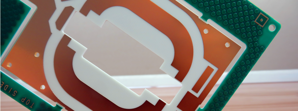
CLTE 0.25mm Double-Sided Rigid PCB Rogers Microwave and RF Printed Circuit Board with Immersion Tin
CLTE 0.25mm Double-Sided Rigid PCB Rogers Microwave and RF Printed Circuit Board with Immersion Tin
Printed Circuit Boards are custom-made products; the images and specifications provided are for reference only.
1. Product Introduction
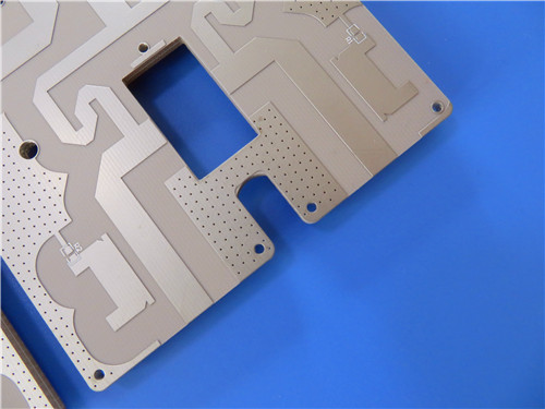
CLTE 2-Layer rigid PCB is a robust microwave printed circuit board built for reliable RF and millimeter-wave electronic systems. This 0.25mm ultra-thin circuit board uses CLTE high-frequency circuit laminates as its core PCB substrate, taking advantage of PTFE-based composite properties to maintain steady electrical performance across changing operating temperatures. Manufactured with immersion tin surface finish and built to IPC-Class-2 requirements, this high-frequency PCB laminate is well suited for compact RF circuit board designs. CLTE PCB material delivers low signal loss and stable dimensional behavior, supporting ground, airborne and radar electronics. This PCB material serves as a trusted composite substrate for high-frequency circuit materials used in automotive, aerospace and communication hardware.
2. Core Product Features
- Loss tangent of 0.0012 at 10 GHz, cutting circuit signal losses while preserving dimensional stability of the high-frequency laminates
- Low Z-axis CTE of 20 ppm/°C, securing excellent plated through-hole reliability for the 2-Layer high-frequency rigid PCB
- Temperature-stable dielectric constant, minimizing mechanical stress when bonding this microwave circuit board to ceramic active components
- Optional heavy metal backing with aluminum, brass or copper for robust embedded resistor network layouts on the PCB substrate
- Precision fabrication with 6/8 mils minimum trace/space and 0.25mm minimum hole size for fine-line microwave PCB board production
- Blind-via-free 2-Layer rigid stackup, simplifying fabrication and improving long-term durability of this printed circuit board
3. Product Performance Benefits
- Stable dielectric performance across thermal cycles, reducing signal drift for high-frequency PCB laminate and RF circuit board applications
- Wide copper cladding compatibility including electrodeposited copper, reverse-treated copper and rolled copper foil to match diverse PCB material requirements
- Exceptional dimensional consistency, one of the lowest performance variances among PTFE-based PCB laminates for embedded resistor designs
- Validated field performance for ground-based and airborne communication plus radar systems, proving the composite substrate’s dependability
- Supports heavy metal backing structures to strengthen embedded resistor networks on high-frequency circuit laminates
4. PCB Construction Details
| Parameter Item | Technical Specification |
| Board Dimensions | 130.6mm x 40mm (1PCS), Tolerance: +/- 0.15mm |
| Minimum Trace/Space | 6/8 mils |
| Minimum Hole Size | 0.25mm |
| Blind Vias Design | No Blind Vias |
| Finished Board Thickness | 0.25mm |
| Finished Copper Weight (Outer Layers) | 1oz (1.4 mils) outer layers |
| Via Plating Thickness | 20 μm |
| Surface Finish | Immersion Tin |
| Top Silkscreen | White |
| Bottom Silkscreen | No |
| Top Solder Mask | Blue |
| Bottom Solder Mask | No |
| Pre-Shipment Testing | 100% Electrical test prior to shipment |
5. PCB Stackup Structure
CLTE 2-Layer rigid printed circuit board adopts a symmetrical dielectric stackup that preserves the electrical integrity of CLTE high-frequency laminates. The layered build maximizes the performance of this high-frequency PCB laminate for RF circuit board manufacturing:
- Copper_layer_1: 35 μm
- CLTE core: 0.135 mm (5.315mil)
- Copper_layer_2: 35 μm
6. PCB Statistical Parameters
This compact layout of the high-frequency composite substrate accommodates dense component placement for miniaturized microwave printed circuit board projects:
- Components: 168
- Total Pads: 93
- Thru Hole Pads: 59
- Top SMT Pads: 34
- Bottom SMT Pads: 0
- Vias: 42
- Nets: 2
7. Artwork Supplied Type
Standard Gerber RS-274-X artwork is provided, fully compatible with global fabrication equipment for high-frequency circuit laminates and precision microwave PCB board manufacturing, supporting accurate patterning and consistent substrate yield.
8. Quality Manufacturing Standard
Rogers CLTE laminate and circuit board is manufactured following IPC-Class-2 industrial specifications. The standard safeguards mechanical and electrical properties of these high-frequency circuit materials for commercial and aerospace RF applications.
9. Product Availability
CLTE 2-Layer microwave PCB is available for worldwide supply. Global customers can access custom fabrication and bulk orders for these high-performance PCB substrates.
10. Typical Application Scenarios
Leveraging low-loss microwave material and thermally stable high-frequency laminates, CLTE RF circuit board fits high-performance automotive, antenna and radio hardware:
- Advanced Driver Assistance Systems (ADAS)
- Patch antennas
- Phased array antennas
- Power amplifiers
11. CLTE Copper Clad Laminate (CCL) Knowledge
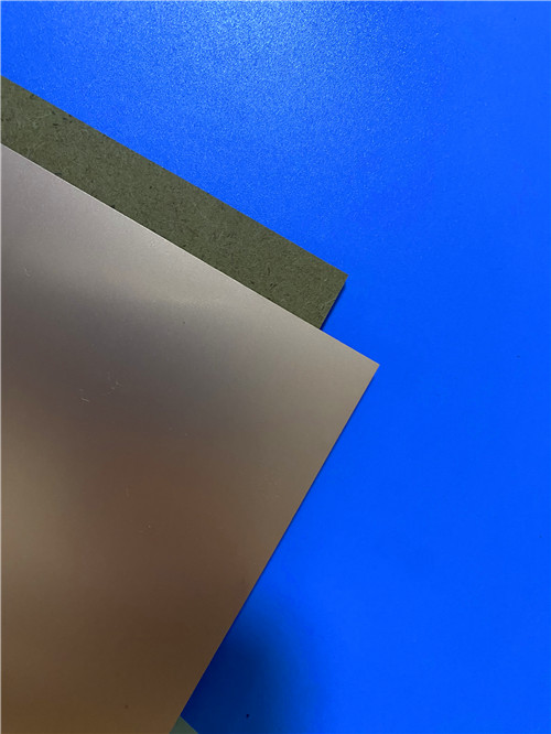
CLTE series high-frequency copper clad laminates are premium core PCB substrate and composite materials engineered for high-end RF, microwave, and millimeter-wave printed circuit board production. These PTFE-derived high-frequency circuit materials deliver outstanding dimensional stability and low planar CTE, delivering predictable performance for embedded resistor structures.
11.1 Core Material Advantages
- Low Performance Variance: CLTE high-frequency laminates feature some of the tightest performance variation of all PTFE-based PCB laminates, ideal for embedded resistor integration on fine-line microwave circuit boards.
- Multiple Copper Cladding Options: With long-proven compatibility with resistor foil, CLTE PCB substrates support electrodeposited copper, reverse-treated copper and rolled copper foil, meeting custom high-frequency circuit material requirements.
- Field-Proven Reliability: CLTE composite laminates are widely adopted microwave material for ground communication hardware, airborne radio equipment and high-precision radar printed circuit boards.
11.2 Key Features and Corresponding Performance Benefits
- Low Loss Tangent: Loss tangent of 0.0012 at 10 GHz, cutting circuit losses without sacrificing dimensional stability of the RF PCB laminate.
- Low Z-axis CTE: 20 ppm/°C low Z-axis CTE improves plated through-hole reliability for the 2-Layer high-frequency rigid PCB and protects against thermal cycling damage.
- Stable Dielectric Constant: Consistent dielectric properties across temperature shifts reduce mechanical stress on ceramic active devices mounted on the microwave circuit board.
- Heavy Metal Backing Option: Custom aluminum, brass and copper backing structures support reliable embedded resistor network designs and reinforce the high-frequency composite substrate.
11.3 Extended Application Scenarios of CLTE Laminate PCB
- Advanced Driver Assistance Systems (ADAS) automotive high-frequency circuit modules
- High-precision patch antenna microwave printed circuit boards
- Phased array antenna system high-frequency rigid PCB substrates
- High-power amplifier RF circuit board modules
12.CLTE Laminate DataSheet
| Properties | Typical Values1 | Units | Test Conditions | Standard | |
| Dielectric Constant (process) | 2.98 | - | 23˚C @ 50% RH, 10 GHz | IPC TM-650 2.5.5.5 | |
| Dielectric Constant (design) | 2.98 | - | C-24/23/50, 10 GHz | Microstrip Differential Phase Length | |
| Dissipation Factor | 0.0021 | - | 23˚C @ 50% RH, 10 GHz | IPC TM-650 2.5.5.5 | |
| Thermal Coefficient of Dielectric Constant | 6 | ppm/˚C | -50 to 150˚C, 10 GHz | IPC TM-650 2.5.5.5 | |
| Volume Resistivity | 1.4 X 10⁹ | Mohm-cm | C-96/35/90 | - | IPC TM-650 2.5.17.1 |
| Surface Resistivity | 1.30 X 10⁶ | Mohm | C-96/35/90 | - | IPC TM-650 2.5.17.1 |
| Electrical Strength (dielectric strength) | 1100 | V/mil | - | - | IPC TM-650 2.5.6.2 |
| Dielectric Breakdown | 64 | kV | D-48/50, X/Y Direction | IPC TM-650 2.5.6 | |
| PIM | - | dBc | 50 ohm 0.060", 43dBm 1900 MHz | - | |
| Decomposition Temperature (Td) | 538 | ˚C | 2hrs @ 105˚C, 5% Weight Loss | IPC TM-650 2.3.40 | |
| Coefficient of Thermal Expansion - x | 9.9 | ppm/˚C | -55˚C to 288˚C | IPC TM-650 2.4.41 | |
| Coefficient of Thermal Expansion - y | 9.4 | ppm/˚C | -55˚C to 288˚C | IPC TM-650 2.4.41 | |
| Coefficient of Thermal Expansion - z | 57.9 | ppm/˚C | -55˚C to 288˚C | IPC TM-650 2.4.41 | |
| Thermal Conductivity | 0.5 | W/(m.K) | z direction | ASTM D5470 | |
| Time to Delamination | >60 | minutes | as-received, 288˚C | IPC TM-650 2.4.24.1 | |
| Copper Peel Strength after Thermal Stress | 1.2 (7) | N/mm (lbs/in) | 10s @288˚C, 35 μm foil | IPC TM-650 2.4.8 | |
| Flexural Strength (MD, CMD) | 92.4, 86.9 (13.4, 12.6) | MPa (ksi ) | 25˚C ± 3˚C | - | ASTM D790 |
| Tensile Strength (MD, CMD) | 73.8, 71.0 (10.7, 10.3) | MPa (ksi ) | 23C/50RH | - | ASTM D638 |
| Flex Modulus (MD, CMD) | 8122, 7984 (1178, 1158) | MPa (ksi ) | 25˚C ± 3˚C | - | ASTM D790 |
| Dimensional Stability (MD, CMD) | -0.07, -0.02 | mm/m | 4 hr at 105˚C | - | IPC-TM-650 2.4.39a |
| Flammability | V-0 | - | C48/23/50 & C168/70 | UL 94 | |
| Moisture Absorption | 0.04 | % | E1/105+D24/23 | - | IPC TM-650 2.6.2.1 |
| Density | 2.31 | g/cm³ | C-24/23/50 | - | ASTM D792 |
| Specific Heat Capacity | 0.60 | J/g˚K | 2 hours at 105˚C | - | ASTM E2716 |
| NASA Outgassing Total Mass Lost | 0.02 | % | - | ASTM E595 | |
| NASA Outgassing Collected Volatiles | 0.00 | % | - | - |
13. Product Summary
CLTE 2-Layer high-frequency rigid PCB is a low-loss printed circuit board built for RF, millimeter-wave and communication applications. This Rogers 0.25mm thin circuit board uses immersion tin surface finish and CLTE high-frequency PCB laminate as its core dielectric. It features stable dielectric behavior, low loss at 10 GHz and strong plated through-hole reliability. Built to IPC-Class-2 standards, this PCB substrate is a versatile microwave material for ADAS, antenna, power amplifier, radar and airborne communication systems.