

 Home
-
Rogers PCB
-
Rogers CLTE-XT PCB 40mil 2-layer High Frequency Circuit Board for RF and microwave applications
Home
-
Rogers PCB
-
Rogers CLTE-XT PCB 40mil 2-layer High Frequency Circuit Board for RF and microwave applications
Rogers CLTE-XT PCB 40mil 2-layer High Frequency Circuit Board for RF and microwave applications
Printed Circuit Boards are custom-made products; the images and specifications provided are for reference only.
General Description
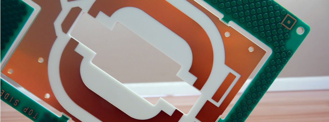
Rogers CLTE-XT PCB is a 40mil (1.016mm) high frequency PCB belonging to the CLTE series—specifically a woven glass reinforced PTFE microwave PCB, designed for high-performance RF and microwave applications.
This is a type of double-sided high frequency PCB built on 40mil (1.016mm) CLTE-XT substrates. The component side of the PCB features a green solder mask and white silkscreen for clear component identification and circuit protection. Its pads are protected by an immersion gold finish, with a minimum of 2 microinches of gold plated over 120 microinches of nickel to ensure strong conductivity and resistance to corrosion.
In terms of dimensions, the boards measure 150mm in length and 65mm in width, with a standard finished copper thickness of 1oz. Fabrication strictly adheres to the IPC-Class-II standard, and every board undergoes 100% open-short circuit testing before shipment to guarantee electrical performance and reliability. For delivery, the PCBs are vacuum-packed, with 25 boards per bag, and each box (containing the vacuum-packed bags) has a total weight of 12 kg.
PCB Specifications
| PCB SIZE | 65mm x 150mm=1 piece |
| BOARD TYPE | High Frequency PCB |
| Number of Layers | 2 layers |
| Surface Mount Components | YES |
| Through Hole Components | N/A |
| LAYER STACKUP | copper ------- 17um(0.5 oz)+plate top layer |
| CLTE-XT 1.016mm | |
| copper ------- 17um(0.5 oz)+plate bot layer | |
| TECHNOLOGY | |
| Minimum Trace and Space: | 12 mil / 12 mil |
| Minimum / Maximum Holes: | 0.4 mm / 4.8 mm |
| Number of Different Holes: | 9 |
| Number of Drill Holes: | 102 |
| Number of Milled Slots: | 1 |
| Number of Internal Cutouts: | 1 |
| Impedance Control: | no |
| Number of Gold finger: | 0 |
| BOARD MATERIAL | |
| Glass Epoxy: | CLTE-XT 1.016mm |
| Final foil external: | 1 oz |
| Final foil internal: | 1 oz |
| Final height of PCB: | 1.2 mm ±0.12 |
| PLATING AND COATING | |
| Surface Finish | Immersion Gold, 43.57% |
| Solder Mask Apply To: | Both sides |
| Solder Mask Color: | Green |
| Solder Mask Type: | Glossy |
| CONTOUR/CUTTING | Routing |
| MARKING | |
| Side of Component Legend | Top side |
| Colour of Component Legend | White |
| Manufacturer Name or Logo: | N/A |
| VIA | Plated through hole(PTH), minimum size 0.4mm. |
| FLAMIBILITY RATING | 94V-0 |
| DIMENSION TOLERANCE | |
| Outline dimension: | 0.0059"" |
| Board plating: | 0.0029"" |
| Drill tolerance: | 0.002"" |
| TEST | 100% Electrical Test prior shipment |
| TYPE OF ARTWORK TO BE SUPPLIED | email file, Gerber RS-274-X, PCBDOC etc |
| SERVICE AREA | Worldwide, Globally. |
Our Advantages
- ISO9001, ISO14001, ISO13485, UL certified manufacturing factory;
- Wide range of PCB laminates option;
- Engineering design prevents problems from occurring in pre-production;
- PCB manufacturing is strictly as per required specifications;
- 16000㎡ workshop; 30000㎡ output capability per month; 8000 types of PCB's per month;
- Quick CADCAM checking and free PCB quotation;
- Rate of qualified products of first production: >99%
- More than 20+ years of high frequency PCB experience;
- A Team with passion, discipline, responsibility and honesty;
- No MOQ, low cost for prototypes and small runs quantity;
Our PCB Capability(2023)
| Parameter | Value |
| Layer Counts | 1-32 |
| Substrate Materials | RO4350B, RO4003C, RO4730G3, RO4360G2, RO4533, RO4534, RO4535, RO4835, RO3003, RO3006, RO3010, RO3035, RO3203, RO3210; RT/Duriod 5880; RT/Duriod 5870, RT/Duriod 6002, RT/Duroid 6010, RT/duroid 6035HTC; RT/duroid 5880LZ; TMM3, TMM4, TMM6, TMM10, TMM10i, TMM13i, Kappa 438; TLF-35; RF-35TC, RF-60A, RF-60TC, RF-35A2, RF-45, RF-10, TRF-45; TLX-0, TLX-6, TLX-7, TLX-8; TLX-9, TLY-3, TLY-5, TLY-5Z; PTFE F4B (DK2.2 DK2.65 DK2.85 DK2.94, DK3.0, DK3.2, DK3.38, DK3.5, DK4.0, DK4.4, DK6.15, DK10.2); AD250C, AD255C, AD300D, AD350A, AD450, AD600, AD1000, TC350; TC600; DiClad 880, DiClad 870, DiClad 527; IsoClad 917; CLTE, CLTE-XT, CLTE-AT, CLTE-MW; Nelco N4000, N9350, N9240; SCGA-500 GF220, SCGA-500 GF255, SCGA-500 GF265, SCGA-500 GF300; FR-4 ( High Tg S1000-2M, TU-872 SLK, TU-768, IT-180A etc.), FR-4 High CTI>600V; Polyimide, PET; Metal Core etc. |
| Maximum Size | Flying test: 900*600mm, Fixture test 460*380mm, No test 1100*600mm |
| Board Outline Tolerance | ±0.0059"" (0.15mm) |
| PCB Thickness | 0.0157"" - 0.3937"" (0.40mm--10.00mm) |
| Thickness Tolerance(T≥0.8mm) | ±8% |
| Thickness Tolerance(t<0.8mm) | ±10% |
| Insulation Layer Thickness | 0.00295"" - 0.1969"" (0.075mm--5.00mm) |
| Minimum Track | 0.003"" (0.075mm) |
| Minimum Space | 0.003"" (0.075mm) |
| Outer Copper Thickness | 35µm--350µm (1oz-10oz) |
| Inner Copper Thickness | 17µm--350µm (0.5oz - 10oz) |
| Drill Hole(Mechanical) | 0.0079"" - 0.25"" (0.2mm--6.35mm) |
| Finished Hole(Mechanical) | 0.0039""-0.248"" (0.10mm--6.30mm) |
| DiameterTolerance(Mechanical) | 0.00295"" (0.075mm) |
| Registration (Mechanical) | 0.00197"" (0.05mm) |
| Aspect Ratio | 12:1 |
| Solder Mask Type | LPI |
| Min Soldermask Bridge | 0.00315"" (0.08mm) |
| Min Soldermask Clearance | 0.00197"" (0.05mm) |
| Plug via Diameter | 0.0098"" - 0.0236"" (0.25mm--0.60mm) |
| Impedance Control Tolerance | ±10% |
| Surface Finish | HASL,HASL LF,ENIG,Immersion Tin,Immersion Silver, OSP, Gold Finger, Pure gold plated etc. |