


 Home
-
Newly shipped PCBs
-
RO4003C and S1000-2M 8-layer 1.6mm Hybrid PCB Rogers ENIG Circuit Board for RF Communication & Automotive Electronics
Home
-
Newly shipped PCBs
-
RO4003C and S1000-2M 8-layer 1.6mm Hybrid PCB Rogers ENIG Circuit Board for RF Communication & Automotive Electronics
RO4003C and S1000-2M 8-layer 1.6mm Hybrid PCB Rogers ENIG Circuit Board for RF Communication & Automotive Electronics
Printed Circuit Boards are custom-made products; the images and specifications provided are for reference only.
1. Introduction
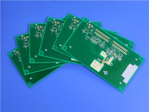
This high-performance 8-layer hybrid rigid PCB adopts a mixed dielectric stackup structure combining Rogers RO4003C high-frequency PCB material and S1000-2M high-reliability FR-4 material, delivering a finished board thickness of 1.6mm and a board dimension of 273mm × 185mm per piece (including process edges). Rogers RO4003C and S1000-2M PCB features a customized copper foil thickness design with 1oz copper for outer layers and a hybrid inner copper configuration of 0.5oz and 1oz, also known as positive-negative copper layout, which balances high-frequency signal transmission performance and structural mechanical stability. For surface finishing, immersion gold treatment is adopted, matched with double-sided green solder mask and white silk screen printing, ensuring clear circuit marking, excellent surface conductivity, corrosion resistance and long-term operational reliability.
Equipped with advanced high-density interconnection and precision hole processing technologies, Rogers 8-layer hybrid PCB supports professional blind hole and resin plug hole craftsmanship. It designs L1-L2 and L7-L8 blind hole structures to optimize internal circuit routing, shorten signal transmission paths and effectively reduce high-frequency signal loss. Meanwhile, precision resin plug holes in 0.2mm, 0.25mm and 0.35mm specifications are applied to eliminate hole gaps, strengthen layer bonding firmness and improve the overall structural integrity of the multi-layer board. All manufacturing processes comply with international industrial standards, making this PCB suitable for high-stability communication and automotive electronic equipment scenarios.
2. PCB Basic Specification Table
Specification Item |
Detailed Parameters |
PCB Layer Count |
8-layer Hybrid Board |
Dielectric Material & Thickness |
Top: 0.203mm RO4003C; Middle: S1000-2M; Bottom: 0.203mm RO4003C |
Finished Board Thickness |
1.6mm |
Outer Layer Copper Weight |
1oz |
Inner Layer Copper Weight |
0.5oz / 1oz (Positive-negative Copper) |
Surface Treatment |
Immersion Gold |
Solder Mask & Printing |
Double-sided Green Solder Mask, White Silk Screen |
Board Dimension |
273mm × 185mm (1PCS, Including Process Edge) |
Special Hole Process |
L1-L2 & L7-L8 Blind Holes; 0.2mm/0.25mm/0.35mm Resin Plug Holes |
3. PCB Stackup Structure
This customized 8-layer hybrid PCB adopts a rational mixed stackup design combining high-frequency RO4003C and high-reliability S1000-2M materials, which balances excellent high-frequency electrical performance and multi-layer structural stability. The layered structure optimizes signal transmission and mechanical endurance, with the detailed stackup configuration displayed below:
4.RO4003C High-frequency Material Introduction
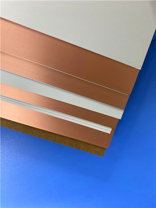
RO4003C is a classic hydrocarbon ceramic laminate belonging to the Rogers RO4000 series, specially engineered for high-frequency and microwave circuit applications. Different from traditional PTFE high-frequency materials, this rigid thermoset dielectric material delivers superior high-frequency performance while supporting standard FR-4 processing, achieving a perfect balance of high performance and cost efficiency for mass production.
The material boasts ultra-stable electrical properties across a wide frequency and temperature range. It features low dielectric tolerance and ultra-low dielectric loss, with a minimal temperature coefficient of dielectric constant, effectively reducing insertion loss for high-frequency signals. Its dielectric constant remains stable even at elevated operating frequencies, making it ideal for broadband RF circuit design. Equipped with optional LoPro foil, it further optimizes high-frequency signal transmission quality and enhances signal integrity.
In terms of structural and processing performance, RO4003C has a copper-matched coefficient of thermal expansion (CTE), providing outstanding dimensional stability, which is critical for hybrid multi-layer PCB construction. Its low Z-axis CTE ensures reliable plated through-hole performance even under severe thermal shock conditions. With a Tg exceeding 280°C, the material maintains stable expansion characteristics throughout the entire PCB processing temperature range. It requires no specialized via treatment such as sodium etch, fully adapting to automated PCB production equipment and standard FR-4 manufacturing workflows, supporting high-volume industrial production. In addition, RO4003C features excellent CAF resistance and repeatable impedance control, ensuring consistent circuit performance.
5.RO4003C Datasheet
Property |
Typical Value |
Direction |
Units |
Condition |
Test Method |
Dielectric Constant εr (Process) |
3.38 ± 0.05 |
Z |
— |
10 GHz / 23°C |
IPC-TM-650 2.5.5.5 Clamped Stripline |
Dielectric Constant εr (Design) |
3.55 |
Z |
— |
8 ~ 40 GHz |
Differential Phase Length Method |
Dissipation Factor tanδ |
0.00270.0021 |
Z |
— |
10 GHz / 23°C2.5 GHz / 23°C |
IPC-TM-650 2.5.5.5 |
Thermal Coefficient of εr |
+40 |
Z |
ppm/°C |
-50°C ~ 150°C |
IPC-TM-650 2.5.5.5 |
Volume Resistivity |
1.7 × 10¹⁰ |
— |
MΩ•cm |
COND A |
IPC-TM-650 2.5.17.1 |
Surface Resistivity |
4.2 × 10⁹ |
— |
MΩ |
COND A |
IPC-TM-650 2.5.17.1 |
Electrical Strength |
31.2 (780) |
Z |
KV/mm (V/mil) |
0.51mm (0.020”) |
IPC-TM-650 2.5.6.2 |
Tensile Modulus |
19,650 (2,850)19,450 (2,821) |
XY |
MPa (ksi) |
Room Temperature |
ASTM D638 |
Tensile Strength |
139 (20.2)100 (14.5) |
XY |
MPa (ksi) |
Room Temperature |
ASTM D638 |
Flexural Strength |
276 (40) |
— |
MPa (kpsi) |
— |
IPC-TM-650 2.4.4 |
Dimensional Stability |
<0.3 |
X, Y |
mm/m (mils/inch) |
After etch + E2 / 150°C |
IPC-TM-650 2.4.39A |
Coefficient of Thermal Expansion |
111446 |
XYZ |
ppm/°C |
-55°C ~ 288°C |
IPC-TM-650 2.4.41 |
Tg (Glass Transition Temperature) |
>280 |
— |
°C |
TMA Method A |
IPC-TM-650 2.4.24.3 |
Td (Decomposition Temperature) |
425 |
— |
°C |
TGA Test |
ASTM D3850 |
Thermal Conductivity |
0.71 |
— |
W/m·K |
80°C |
ASTM C518 |
Moisture Absorption |
0.06 |
— |
% |
48 hrs immersion, 0.060” sample, 50°C |
ASTM D570 |
Density |
1.79 |
— |
g/cm³ |
23°C |
ASTM D792 |
Copper Peel Strength |
1.05 (6.0) |
— |
N/mm (pli) |
After solder float, 1 oz. EDC Foil |
IPC-TM-650 2.4.8 |
Flammability |
N/A |
— |
— |
— |
UL 94 |
Lead-Free Process Compatible |
Yes |
— |
— |
— |
— |
6.RO4003C Application Fields
Thanks to its reliable high-frequency performance and cost-effective manufacturability, RO4003C materials are widely applied in commercial and industrial RF/microwave electronic devices. Its core application scenarios include cellular base station antennas and power amplifiers, RF identification systems, automotive radar and sensor modules, as well as low-noise block downconverters for satellite direct broadcast systems. It is the preferred substrate for high-frequency broadband circuits, controlled impedance transmission lines and filter design products.
7. S1000-2M FR-4 Material Introduction
S1000-2M (including S1000-2MB) is a high-performance lead-free FR-4 dielectric material with low CTE and high Tg characteristics, specially optimized for high-layer-count multi-layer PCB manufacturing. This premium substrate material solves the structural stability challenges of complex multi-layer boards, featuring excellent mechanical processing performance and thermal resistance, fully compatible with modern lead-free assembly processes.
The material exhibits prominent advantages in reliability and environmental adaptability. Its low Z-axis CTE greatly improves through-hole structural reliability, effectively avoiding hole cracking and layer delamination during long-term use and thermal cycling. It delivers superior PCT performance with ultra-low water absorption, enabling stable operation under high temperature and high humidity working conditions. With excellent mechanical strength and thermal stability, it adapts to complex multi-layer pressing and high-precision processing requirements of high-density PCBs.
8. S1000-2M Datasheet
Items |
Condition |
Unit |
Spec Requirement |
Typical Value |
Tg |
DMA |
℃ |
≥ 180 |
185 |
Flammability |
C-48/23/50, E-24/125 |
Rating |
V-0 |
V-0 |
Volume Resistivity |
After moisture resistance |
MΩ-cm |
≥ 10⁶ |
6.79×10⁷ |
Volume Resistivity |
E-24/125 |
MΩ-cm |
≥ 10³ |
2.19×10⁸ |
Surface Resistivity |
After moisture resistance |
MΩ |
≥ 10⁴ |
3.16×10⁶ |
Surface Resistivity |
E-24/125 |
MΩ |
≥ 10³ |
2.24×10⁷ |
Arc Resistance |
D-48/50+D-0.5/23 |
S |
≥60 |
133 |
Dielectric Breakdown |
D-48/50+D-0.5/23 |
kV |
≥40 |
45kV+NB |
Dielectric Constant @ 1GHz |
C-24/23/50 |
— |
— |
4.6 |
Dielectric Constant @ 1MHz |
C-24/23/50 |
— |
≤5.4 |
4.9 |
Dissipation Factor @ 1GHz |
C-24/23/50 |
— |
— |
0.018 |
Dissipation Factor @ 1MHz |
C-24/23/50 |
— |
≤0.035 |
0.015 |
Thermal Stress |
288℃, solder dip |
— |
>10s, No Delamination |
>100s, No Delamination |
Peel Strength (1 Oz) |
288℃/10s |
N/mm |
≥ 1.05 |
1.3 |
Flexural Strength (LW) |
— |
MPa |
≥415 |
567 |
Flexural Strength (CW) |
— |
MPa |
≥345 |
442 |
Water Absorption |
D-24/23 |
% |
≤0.5 |
0.08 |
CTE(Z-axis) Before Tg |
— |
PPM/℃ |
≤60 |
41 |
CTE(Z-axis) After Tg |
— |
PPM/℃ |
≤300 |
208 |
Z-axis Thermal Expansion 50–260℃ |
— |
% |
≤3.0 |
2.4 |
Td (5% weight loss) |
— |
℃ |
≥340 |
355 |
T260 (TMA) |
— |
min |
≥30 |
60 |
T288 (TMA) |
— |
min |
≥5 |
30 |
T300 (TMA) |
— |
min |
≥2 |
15 |
CTI |
IEC60112 Method |
V |
PLC3(175~250) |
PLC3 (200V) |
9. S1000-2M Application Fields
S1000-2M is widely utilized in high-layer-count, high-reliability PCB products. It is extensively applied in high-end computing equipment, communication infrastructure devices, automotive electronic systems and other precision electronic fields. Its outstanding thermal stability and structural reliability make it an ideal core dielectric material for hybrid high-frequency multi-layer PCBs, effectively complementing the high-frequency performance of RO4003C materials and improving the overall yield and service life of finished circuit boards.
10. Summary
This 8-layer 1.6mm hybrid PCB adopts a premium combination of RO4003C high-frequency ceramic hydrocarbon material and S1000-2M high-reliability FR-4 material, integrating the high-frequency signal advantages of Rogers substrates and the structural stability of high-performance FR-4 materials. With a scientific mixed stackup design, positive-negative hybrid copper thickness configuration, immersion gold surface treatment, and precision blind hole and multi-specification resin plug hole processes, RO4003C hybrid PCB achieves excellent signal integrity, structural firmness and environmental adaptability. RO4003C and S1000-2M PCB supports high-frequency broadband signal transmission and high-temperature and high-humidity working environments, perfectly meeting the manufacturing standards and application demands of RF communication, automotive electronics and high-precision computing equipment in European and American markets.
Tags: RO4003C Hybrid PCB, Rogers 8-layer 1.6mm PCB, S1000-2M FR4 PCB, Immersion Gold PCB, RO4003C High Frequency PCB, RO4003C and S1000-2M PCB, Rogers RO4003C Multilayer PCB, Automotive Electronic PCB, High Layer Count PCB